EasyManua.ls Logo

LSLIDAR CH128X1 - 2.2 Cable Connections

LSLIDAR CH128X1
44 pages
Print Icon
To Next Page IconTo Next Page
To Previous Page IconTo Previous Page
Loading...
5
recommended to use a 220VAC adapter nearby for power supply (DC long-
distance power supply is not recommended).
2.2 Electrical Interface
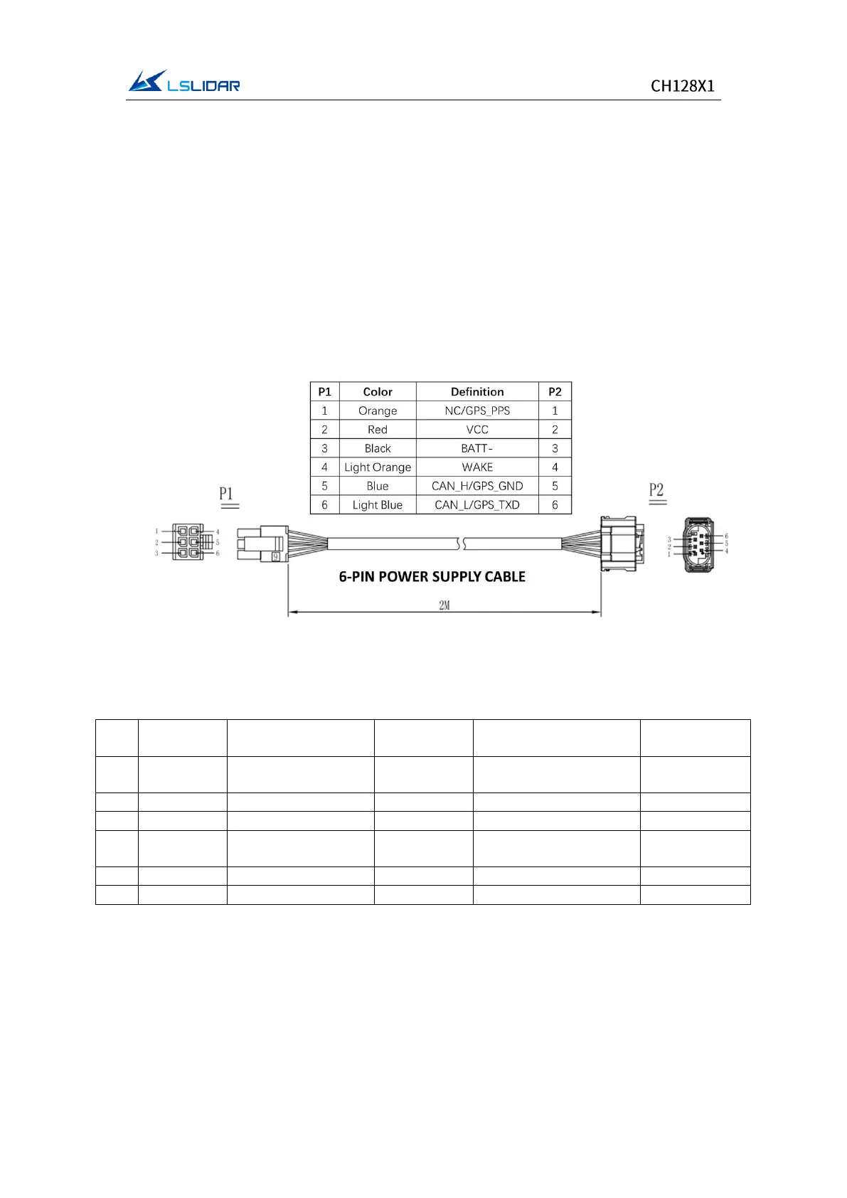
The cables from the side of the CH128X1 lidar base are a 6-pin power supply
cable and a 2-pin automotive ethernet cable. The cables are as shown in the
figures below.
Note: There are two types of power supply cables (only differ in wire colors) for
random shipments.
Figure 2.1 The 6-PIN Power Supply Cable
Table 2.1 Wiring Definition of the 6-PIN Power Supply Cable
S/N
Color
Definition (for lidar
with CAN protocol)
Description
Definition (for lidar
with GPS time service)
Description
1
Orange
NC
-
GPS_PPS
GPS Inputting
PPS Signal
2
Red
VCC
Power+
VCC
Power+
3
Black
BATT-
Power-
BATT-
Power-
4
Light
Orange
Wake
Wake-up
Input Signal
Wake
Wake-up
Input Signal
5
Blue
CAN_H
CAN_H
GPS_GND
GPS_GND
6
Light Blue
CAN_L
CAN_L
GPS_TXD
GPS_TXD