N10 PLUS
5
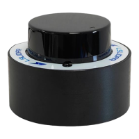
Figure 1.7 Adapter Board
Note:
POWER DATA: data communication and system power supply.
LIDAR: connection to lidar.
2 Electrical Parameters
The N10 PLUS lidar communicates with serial port of 3.3 V. An N10 PLUS lidar
is made of a high frequency ranging core, a wireless transmission system, and a
rotating subsystem. The rotating subsystem is driven by a brushless DC motor
spinning inside the system. The signal cable of N10 PLUS can be interfaced with
the UART port of the FPGA/DSP/ARM/SCM without the need for the
conversion of RS232, 422 chips. You connect an external system and the lidar
and follow the communication protocol of the lidar system to obtain the scanned
point cloud data, device information and status, and set the working mode in
real-time.
Table 2.1 Electrical Parameters
The power supply not in the
range may lead to inaccurate
ranging or irreversible damage.