ISR 12-LO • IGAR 12-LO Operating Manual Introduction • 12
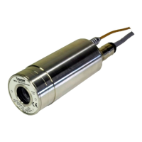
2.5 Physical User Interface
Pyrometer Interior view pyrometer housing
1 Display for clear mode
2 Display °C or °F
3 LED display for temperature or parameters
4 Display for measuring mode
5 Mounting screws for cover (4 units)
6 Fiber optic
7 Optical head
9 Parameter indicator
10 Interface switch
11 Push button for test current
12 Setting keys
13 Electrical connection
14 Connection for fiber optic
15 Mounting holes
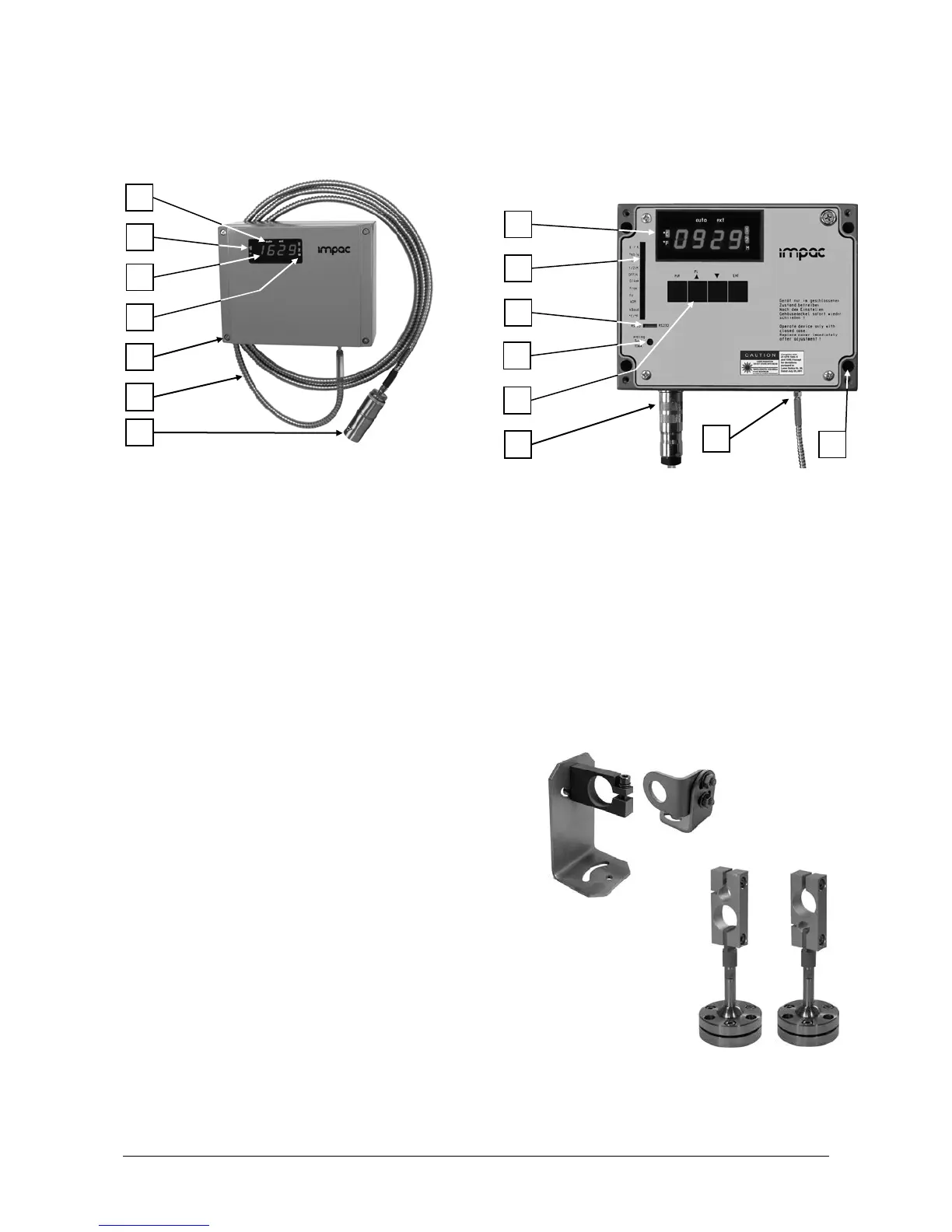
2.6 Accessories (Optional)
Numerous accessories guarantee easy installation of the pyrometer. The following overview
shows a selection of suitable accessories. You can find the entire accessory program with all
reference numbers in Chapter 8, Reference numbers.
Mounting:
For mounting and aligning the pyrometer to the
measured object mounting angles or a
socket mounting is available. The
mounting is an easy way to a
the measured object. The clamping-
screws of the ball
and socket mounting enable an easy and fast
adjustment of the pyrometer in all directions.

 Loading...