ISR 12-LO • IGAR 12-LO Operating Manual Controls and Connections • 15
3 Controls and Connections
3.1 Electrical Installation
The ISR 12-LO and the IGAR 12-LO are powered by a voltage of 24 V DC (15 to 40 V DC) or
24 V AC (12 to 30 V AC). As the instrument is operating with heated and thermostatically
controlled sensors, it needs a warm-up of up to 5 minutes (during this warm-up period the LED
display indicates “7777“), after that the instrument is ready for use. To switch off the
instrument, interrupt the power supply or unplug the electrical connector.
To meet the electromagnetic requirements (EMV), a shielded connecting cable must be used.
The shield of the connecting cable must be connected only on the pyrometer’s side. On side of
the power supply (switch board) the shield must be open to avoid ground loops.
LumaSense offers connecting cables; they are not part of standard scope of delivery. The main
connecting cable has wires for power supply, interface, analog output, external laser switch and
external clear of maximum value storage via contact (see section 8, Reference numbers) and
12 pin connector. The cable includes a short RS232 adapter cable with a 9 pin SUB-D connector
for direct PC communication. This adapter is not used in combination with RS485 interface.
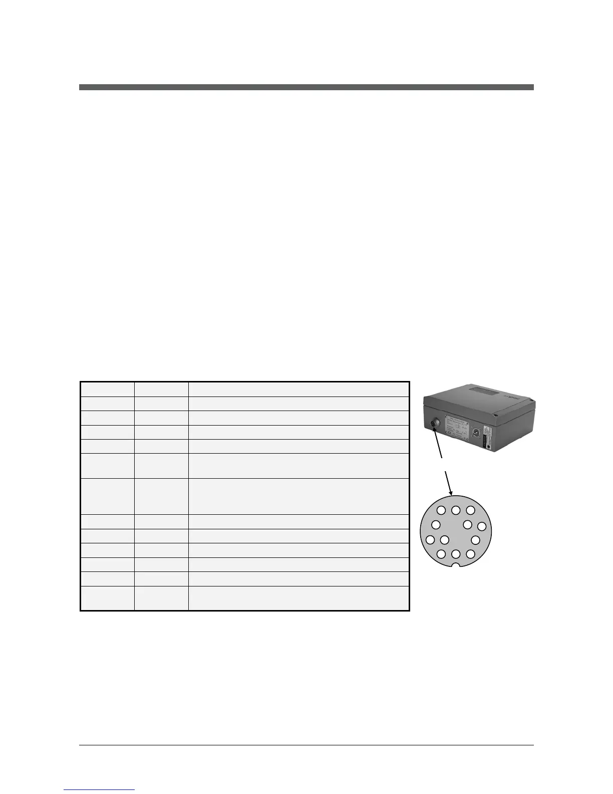
3.2 Pin assignment of the male socket on the back of the
pyrometer
Pin Color Indication
G red DGND (Ground for interface)
F black RxD (RS232) or B1 (RS485)
C violet TxD (RS232) or A1 (RS485)
D gray/pink B2 (RS485) (bridge to F)
E red/blue A2 (RS485) (bridge to C)
M orange

 Loading...