IS 12 / IGA 12 Manual Controls and Installation • 15
3 Controls and Installation
3.1 Electrical Installation
The pyrometers are powered by a voltage of either 24 V DC (15 to 40 V DC) or 24 V AC
(12 to 30 V AC), 48 to 62 Hz. Once connected to power, the instrument operations immediately
and needs no warm-up time. To switch off the instrument, unplug the connector.
To meet the electromagnetic requirements, a shielded connecting cable must be used. The
shield of the connecting cable has to be connected only on the pyrometer side to avoid ground
loops.
LumaSense offers connecting cables, but they are not part of
standard scope of delivery. The main connecting cable has wires
for power supply, interface, analog output, external laser switch
and external clear of maximum value storage via contact (see
Chapter 10, Reference numbers) and 12 pin angle connector.
The cable includes a short RS232 adapter cable with a 9 pin
SUB-D connector for direct PC communication. This adapter is
not used in combination with RS485 interface.
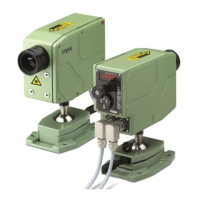
For use of the limit contacts, the separate additional cable has
connector connector
for main for additional cable
connection cable for limit switches
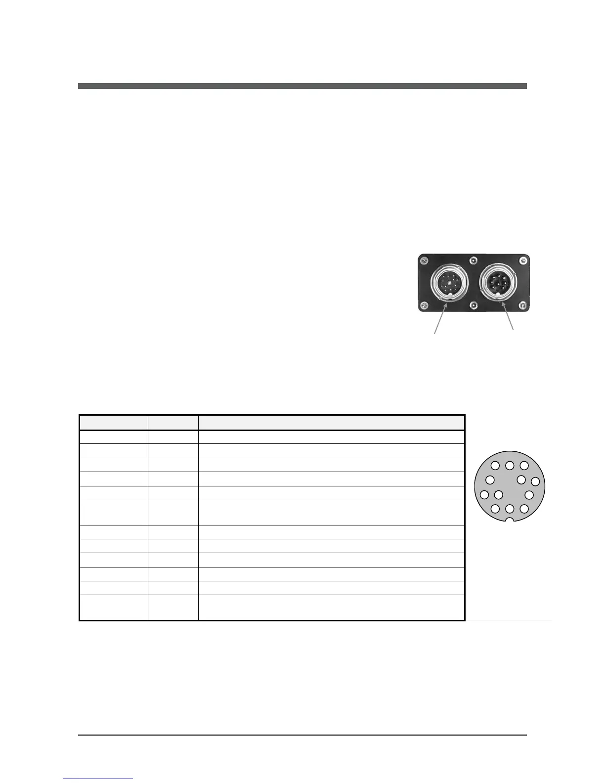
3.1.1 Pin assignment for the connector on the back of the pyrometer
For the main connection cable
Pin Color Indication
*
)
For setting of clear time to "extern" (see 5.3, clear time for maximum value storage).
For additional limit contacts cable
The instrument is equipped with two independent relay limit switches. These are two separate
switch-over relay contacts, changing its state if the adjusted temperatures are exceeded.
 Loading...