14
of harmonic energy, harmonic percentage values are displayed.
Through
and push-buttons, one can switch between suc-
cessive harmonics. The harmonic no is alternately displayed with the
value. Through the RS-485 interface one can set up the values, that
would be visualized (starting from version 1.02).
The error display is described in the chapter 8.
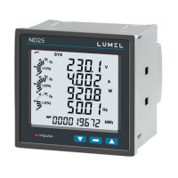
When displaying the reactive power, a marker indicating the load cha-
racter is displayed, capacitive ( ) or inductive ( )
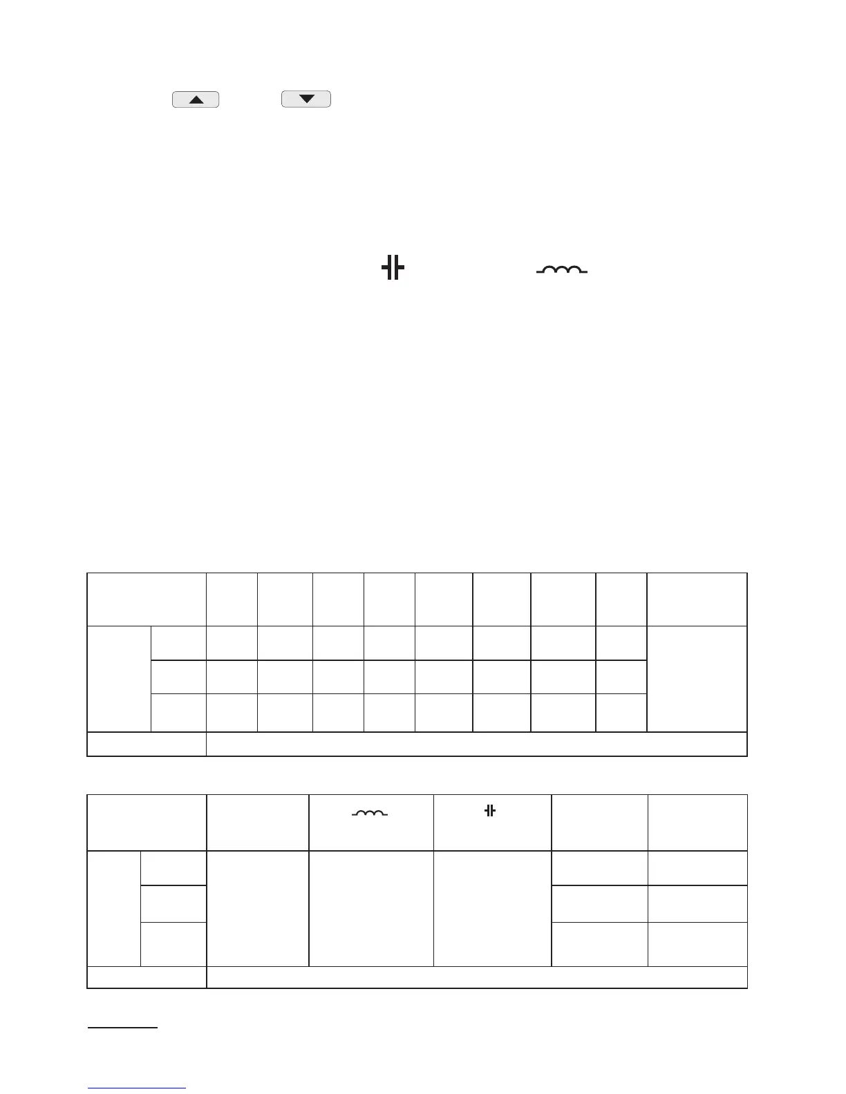
Table 1a
Backlit symbols
L1, V
L2, V
L3, V
L1-2, V
L
2-3, V
L
3-1, V
L
1, A
L
2, A
L
3, A
L
1, W
L
2, W
L
3, W
L
1, Var
L
2, Var
L
3, Var
L
1, VA
L
2, VA
L
3, VA
L
1, PF
L
2, PF
L
3, PF
L
1, tg
L
2, tg
L
3, tg
kWh
Displayed values
row 1 U1 U12
1
I1 P1 Q1 S1 PF1 tg1
Imported
active
energy2
EnP
row 2 U2
1
U23
1
I2
1
P2
1
Q2
1
S2
1
PF2
1
tg2
1
row 3 U3
1
U31
1
I3
1
P3
1
Q3
1
S3
1
PF3
1
tg3
1
Displaying
optional
Backlit symbols -, kWh
kVarh kVarh
L
1, U/ THD U
L
2, U/ THD U
L
3, U/ THD U
L
1, I/ THD I
L
2, I/ THD I
L
3, I/ THD I
Displayed values
row 1
Exported
active
energy 2
reactive inductive
energy
/
reactive positive
energy
2
reactive
capacitive energy
/
reactive negative
energy
2
Uh1 V /
THD1 %
Ih1 A/
THD1 %
row 2
Uh2 V /
THD2 %
1
Ih2 A/
THD2 %
1
row 3
Uh3 V /
THD3 %
1
Ih3 A/
THD3 %
1
Displaying
optional
Displayed quantities in the field 9 (fig. 4.) for 3-phase 4-wire measu-
rement mode 3Ph/4W and single-phase 1Ph/2W are presented in the
table 1a and 1b.
 Loading...