To download the updated software, multilingual manuals,
and Quick Start Guide, please visit Lumens™ website at:
。https://www. /supportMyLumens.com
Please activate your warranty: 。www.MyLumens.com/reg
Important
www.MyLumens.com
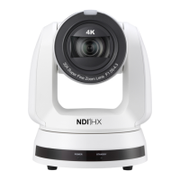
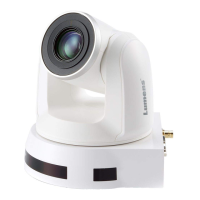
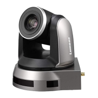
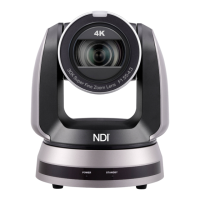
1. Product Introduction
3. About the power supply
1.1 Product Overview
1.2 I/O Interface
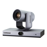
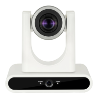
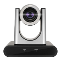
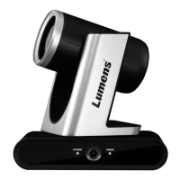
Panoramic Camera
Copyright ©2020 Lumens Digital Optics Inc. All rights reserved.
Tracking
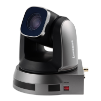
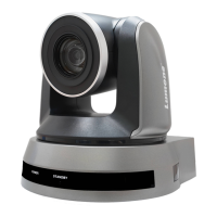
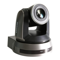
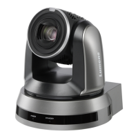
PTZ Camera
2. Instruction on OUTPUT SWITCH Setting
LED Indicator IR Remote
DIP Switch
Reserved
Hole
USB
SDI
Output
Power
(DC12V)
LAN Port
Audio
Input
HDMI
Output
RS-232
Input
Power
Switch
OFF
ON
2.1 Factory-preset default is 1080p60.
2
because they cannot be output at
the same time.
2.3 The camera will restart 5 seconds
after modifying the DIP.
2. USB and IP may only choose one,
Router
Camera
CAT6 network cable
3.1 Connect the DC 12 V power adapter for power supply.
3.2 Access power by using a router that supports PoE or connecting to a
HUB with an Internet cable.
4. Installation Precautions
4.1 Recommended best tracking target distance
4.2 Recommended best mounting height: 2.2 ~ 2.4 m
: 8~12m
4.3 To install the camera on the wall or ceiling, the accessories could be
bought separately.
5. Camera connection description
CMS Software
Camera
LAN
CAT5e/
network cable
CAT6
The camera supports PoE+(IEEE802.3at)
5100401-50 OCT. 2020
When all the DIP switches are set to ON,
the resolution of the camera is determined
by OSD.
CAT5e/
network cable
CAT6
8m~12m
2.2m~2.4m
Auto-Tracking Camera
Quick Start Guide