A-12
CDD3000-HF Operation Manual
A.5 UL approbation
Measures to maintain UL approbation
1. Switch cabinet mounting with IP54 protection and contamination
level 2 is mandatory.
2. The devices are only usable in systems with surge strength class III.
3. Only UL approved fuses and circuit-breakers may be used.
CDD32.xxx-HF : Mains fuses min. 250 V H or K5
CDD34.xxx-HF : Mains fuses min. 600 V H or K5
4. The devices are usable in systems with a maximum current capacity
of 5000 A.
5. The connecting cables (mains power, motor and control cables) must
be UL approved.
CDD32.xxx-HF : Min. 300 V cables (mains/motor), Cu 75° C min.
CDD34.xxx-HF : Min. 600 V cables (mains/motor), Cu 75° C min.
Attention: The drive controllers can typically be overloaded with 1.8 x I
N
for 30 s. The effective servo capacity utilization (I
eff.
≤ I
N
)
must never be greater than I
N
(rated current).
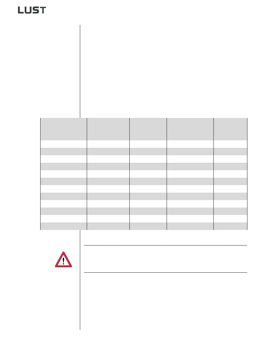
Tightening torque of
grounding lead
terminal [Nm]
Tightening torque
of mains terminals
[Nm]
Device Wire cross-section Mains fuse
0.5 ... 0.6 0.5 ... 0.6 CDD32.004-HF AWG 16 N/M 10 A
0.5 ... 0.6 0.5 ... 0.6 CDD32.006-HF AWG 14 N/AWG 16 M 10 A
0.5 ... 0.6 0.5 ... 0.6 CDD32.008-HF AWG 14 N/AWG 16 M 20 A
0.5 ... 0.6 0.5 ... 0.6 CDD34.003-HF AWG 16 N/M 10 A
0.5 ... 0.6 0.5 ... 0.6 CDD34.005-HF AWG 16 N/M 10 A
0.5 ... 0.6 0.5 ... 0.6 CDD34.006-HF AWG 16 N/M 10 A
0.5 ... 0.6 0.5 ... 0.6 CDD34.008-HF AWG 14 N/M 15 A
0.5 ... 0.6 0.5 ... 0.6 CDD34.010-HF AWG 14 N/M 15 A
0.5 ... 0.6 0.5 ... 0.6 CDD34.014-HF AWG 12 N/M 20 A
0.5 ... 0.6 0.5 ... 0.6 CDD34.017-HF AWG 12 N/M 25 A
1.2 ... 1.5 1.2 ... 1.5 CDD34.024-HF AWG 10 N/M 30 A
1.2 ... 1.5 1.2 ... 1.5 CDD34.032-HF AWG 8 N/M 50 A
Table A.4 Cable cross-sections - mains (N), motor (M)
 Loading...