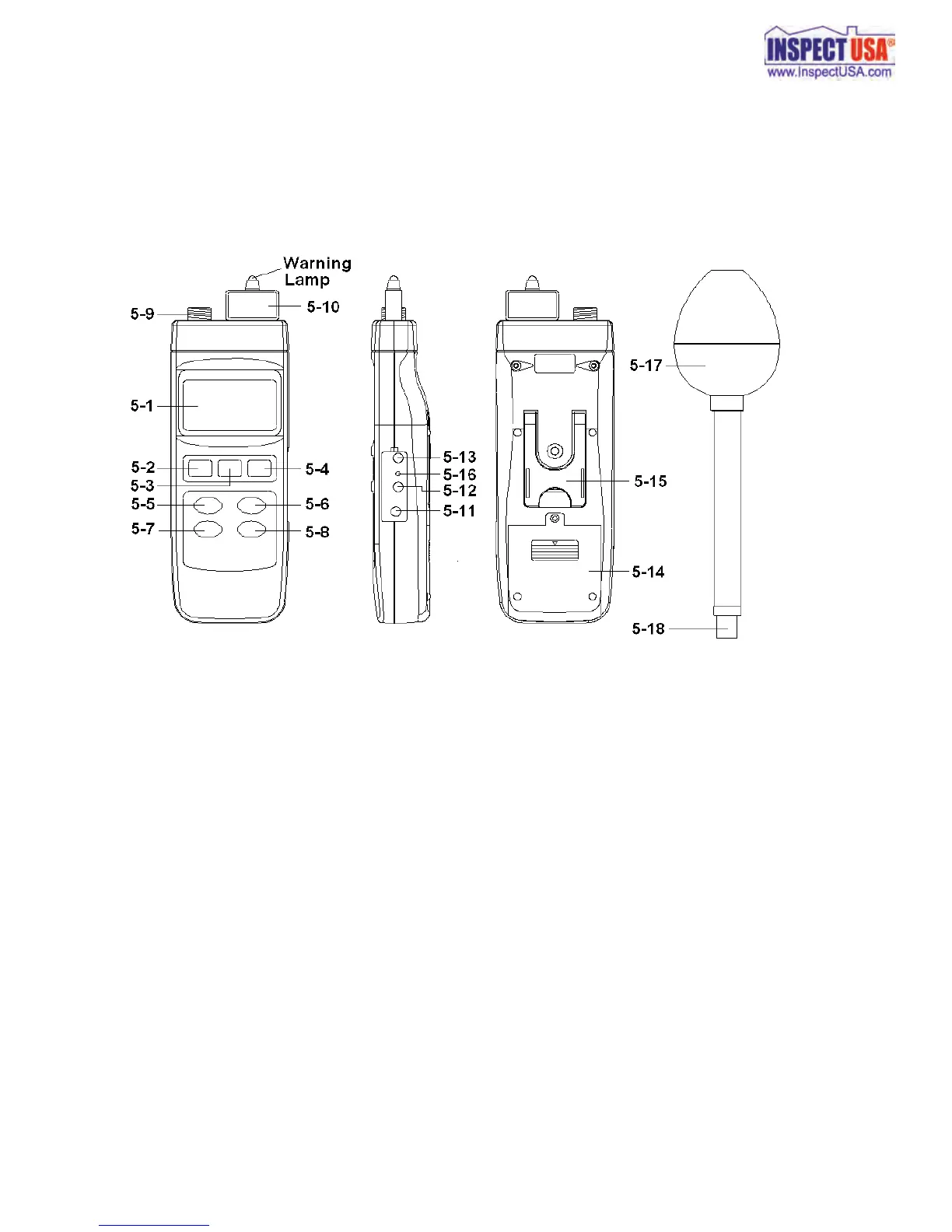
5. FRONT PANEL DESCRIPTION
Fig. 1
5-1 Display 5-10 Probe Memory Card
5-2 Power Button 5-11 DC Adapter Input Socket
5-3 Hold / ESC Button 5-12 RS-232 Output Terminal
5-4 REC / Enter Button 5-13 LCD contrast adj.
5-5 Freq. Team Button 5-14 Battery Cover
5-6 Unit Button 5-15 Stand
5-7 Peak Hold Button 5-16 Reset Button
5-8 Alarm Set / Start Button 5-17 Probe Sensing Head
5-9 Probe Input Socket 5-18 Probe Plug
6