Do you have a question about the Luxman E-250 and is the answer not in the manual?
Install unit in a location with good ventilation and heat radiation, avoiding direct sunlight or humid/dusty areas.
Unit has a time muting circuit; sound is delayed after power-on. Set volume low initially.
Ensure secure grounding for cartridges and components to prevent hum and noise.
Consult dealer for repairs. Use a soft cloth for cleaning; avoid solvents like benzine or thinner.
NF type phono equalizer supporting MM/MC, featuring selected MC transformers, improved S/N ratio, selector relays.
Offers 4-position load impedance and load capacity settings for cartridge compatibility and tone adjustment.
Includes Articulation function for demagnetization, a Low Cut switch for warped records, and Stereo/Monaural mode.
Features compact chassis, original OFC wires for signal transmission, RCA input/output terminals, and an AC inlet.
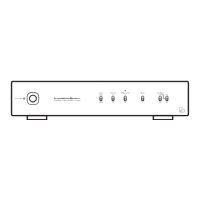
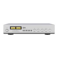
Details operation switch, indicator, mode switch, low cut switch, and articulator switch for unit control.
Articulator indicator blinks when the articulator function is active.
Selects input terminals (1/2), cartridge type (MM/MC), and MC impedance (HIGH/LOW).
Covers input impedance/capacitor selection, signal ground, input/output terminals, and AC inlet for connectivity.
Connect accessory power cable to AC inlet and turn off all unit power before connecting devices.
Connect the AC plug of the accessory power cable to a wall outlet in the listening room.
Connect output terminals to line input of control/integrated amplifier. Do not connect to phono input.
Connect tone arm RCA cables to input terminals and ground wires to ground terminals securely.
| Type | Phono Preamplifier |
|---|---|
| Input Sensitivity (MM) | 2.5 mV |
| Input Impedance (MM) | 47 kΩ |
| Input Impedance (MC) | 100 Ω |
| Gain (MM) | 40 dB |
| Gain (MC) | 60 dB |
| THD | 0.005% |