Names and Functions
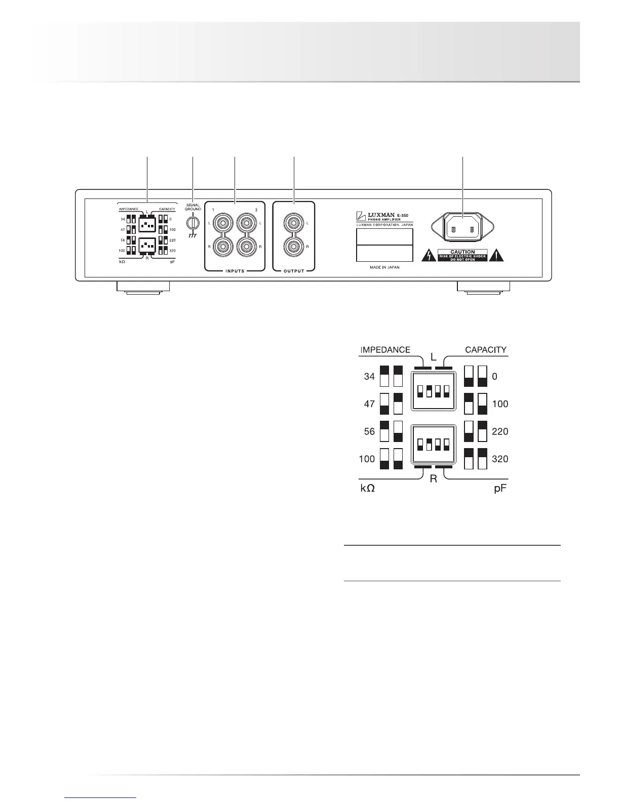
10. Input impedance selector/
input capacitor selector
The input impedance and input capacitor can be selected
according to your cartridge. The switches in the upper row
are used for the L channel, and the switches in the lower
row are used for the R channel.
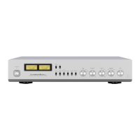
The switches 1 and 2 are used for the input impedance, and
the switches 3 and 4 are used for the input capacitor.
Combination of the switches shown in the figure allows the
setting at the L and R channels to be performed at the same
time according to your cartridge specifications or your fa-
vorite pattern.
For the input impedance, 34 kΩ, 47 kΩ, 56 kΩ and 100 kΩ
are selectable, and for the input capacitor, 0 pF, 100 pF,
220 pF, and 320 pF are selectable.
The input impedance is 47 kΩ and the input capacitor is
0pF as factory default settings.
ON
1 2 3 4
ON
1 2 3 4
* Switch positions are marked with ■ in the detailed drawing
above.
Before changing switch positions, set the sound volume of
connected devices to a low level.
Rear panel