EasyManua.ls Logo

M-system 53U User Manual

M-system 53U
52 pages
To Next Page IconTo Next Page
Page #1 background imageLoading...
Page #1 background image
5-2-55, Minamitsumori, Nishinari-ku, Osaka 557-0063 JAPAN
Phone: +81(6)6659-8201 Fax: +81(6)6659-8510 E-mail: info@m-system.co.jp
EM-6485-B Rev.21 P. 1 / 52
OPERATING MANUAL
CONTENTS
BEFORE USE .... ........................................................................................................... 2
POINTS OF CAUTION ................................................................................................ 2
PERFORMANCE ............................................................................................................ 3
COMPONENT IDENTIFICATION .......................................................................................... 4
EXTERNAL DIMENSIONS unit: mm (inch) ............................................................................. 5
TERMINAL CONNECTIONS ............................................................................................... 6
COMMUNICATION CABLE CONNECTION ............................................................................... 8
SYSTEM CONFIGURATION EXAMPLES ................................................................................. 9
MODBUS - BASICS ...................................................................................................... 10
MODBUS - OPERATIONS ............................................................................................... 11
MODBUS - SETTING ..................................................................................................... 13
MODBUS - MEASURED VARIABLES .................................................................................. 27
OPERATION FLOWCHART .............................................................................................. 40
SETTING EXAMPLES .................................................................................................... 50
ERROR MESSAGES ...................................................................................................... 52
MAINTENANCE ........................................................................................................... 52
LIGHTNING SURGE PROTECTION ..................................................................................... 52
MULTI POWER MONITOR
(4 digital displays)
MODEL
53U

Other manuals for M-system 53U

Question and Answer IconNeed help?

Do you have a question about the M-system 53U and is the answer not in the manual?

M-system 53U Specifications

General IconGeneral
BrandM-system
Model53U
CategoryMonitor
LanguageEnglish

Summary

Points of Caution

CAUTION

General warning about improper use impairing protection.

CONFORMITY WITH EU DIRECTIVES OR UL

Details EU directives, measurement/installation categories, and insulation classes.

AUXILIARY POWER SUPPLY RATING & OPERATIONAL RANGE

Specifies auxiliary power supply ratings and operational ranges for AC and DC.

GENERAL PRECAUTION

Safety advice before removing or mounting the unit.

SYMBOLS USED ON THE PRODUCT AND IN THIS MANUAL

Explains symbols indicating user manual reference and double insulation.

PERFORMANCE

Accuracy

Specifies accuracy for voltage, current, power, frequency, and energy measurements.

INPUT

Details input frequency, voltage, current, and auxiliary power supply ratings.

OUTPUT

Describes Modbus interface, DC current/voltage outputs, and open collector types.

COMPONENT IDENTIFICATION

FRONT VIEW

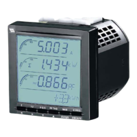
Identifies front panel components like data displays and control buttons.

REAR VIEW

Identifies rear panel components like terminals and configurator jack.

CONTROL BUTTON OPERATIONS

Explains button functions for normal and setting modes.

HOW TO CHANGE VALUES

Step-by-step guide to changing displayed values like current.

EXTERNAL DIMENSIONS unit: mm (inch)

PANEL CUTOUT unit: mm (inch)

Provides panel cutout dimensions for mounting the unit.

WIRING

Details wiring requirements for current, voltage, and other connections.

CONNECTING TO POWER SOURCE

Instructions for connecting the power supply cable safely.

TERMINAL CONNECTIONS

COMMUNICATION CABLE CONNECTION

SYSTEM CONFIGURATION EXAMPLES

RS-485/RS-232-C

Example configuration using RS-485/RS-232-C converter and surge protector.

RS-485/ETHERNET

Example configuration using RS-485/ETHERNET adapter and surge protector.

MODBUS - BASICS

COMM. PROPERTY

Lists selectable Modbus communication parameters like baud rate and parity.

FUNCTION CODE

Details Modbus function codes for reading and writing registers.

MODBUS - OPERATIONS

MODBUS REGISTER ACCESS SETTING

Settings for controlling Modbus register writing protection via passcode.

USER OPERATIONS

Operations like key lock, display switching, and alarm trip reset.

MODBUS - SETTING

SYSTEM OPERATIONS

Settings for system configuration like tariff, reboot, and passcode.

MODBUS SETTING

Settings for Modbus communication parameters like address and baud rate.

MODBUS - MEASURED VARIABLES

OPERATION FLOWCHART

DISPLAY

Shows display symbols, measurands, units, and line views.

HOW TO SWITCH THE DISPLAY VIEWS

Guides on switching between different parameter views using buttons.

SETTING EXAMPLES

SETTING INPUT CONFIGURATION

Example for setting input configuration for a 3-phase system.

SETTING ANALOG OUTPUT

Examples for setting analog outputs for voltage, current, power, PF.

ERROR MESSAGES

ERROR MESSAGES

Lists system errors (ERR) and their causes/solutions.

OL FIU

Explains overload input errors (OL) and their causes/solutions.

MAINTENANCE

Instructions for cleaning the unit with a dry cloth.

LIGHTNING SURGE PROTECTION

Information on M-System's lightning surge protectors.