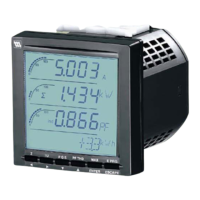
53U
5-2-55, Minamitsumori, Nishinari-ku, Osaka 557-0063 JAPAN
Phone: +81(6)6659-8201 Fax: +81(6)6659-8510 E-mail: info@m-system.co.jp
EM-6485-B Rev.21 P. 5 / 52
EXTERNAL DIMENSIONS unit: mm (inch)
96 (3.78) 92 (3.62)
92 (3.62)
80 (3.15) [12 (.47)]23 (.91)
2 (.08)
96 (3.78)3 (.12) 3 (.12)
MOUNTING BRACKETGASKET
100 (3.94) dia.
92
+
0.8 (3.65)
0 (3.63)
92
+
0.8 (3.65)
0 (3.63)
■ PANEL CUTOUT unit: mm (inch)
Panel thickness : 2 to 15 mm (0.08 to 0.59 inch)
■ WIRING
• Current input
Applicable cable size: ≤ 2.4 mm dia., 0.5 to 3.5 mm
2
Stripped length: 13 to 15 mm
• Voltage input
Applicable cable size: ≤ 2.5 mm dia., 0.5 to 3.5 mm
2
Stripped length: 7 to 8 mm
• Contact input, contact output, analog output, Modbus,
auxiliary power
Applicable cable size: ≤ 2.4 mm dia., 0.5 to 2.5 mm
2
Stripped length: 7 to 8 mm
■ CONNECTING TO POWER SOURCE
• Confirm the auxiliary power supply rating on the speci-
fications.
Rated voltage
AC Power 100 – 240 V AC
DC Power*
1
110 – 240 V DC
• How to Connect the power supply cable:
1) Confirm that the power supply is turned off.
2) Pull and remove the terminal block marked U(+) and
V(–)*
2
from the 53U.
3) Loosen two (2) screws corresponding to U(+) and V(–)*
2
at
the terminal block.
4) Insert wires into the connection.
5) Fix them with the screw.
6) Replace the terminal block back into the 53U.
*1. UL approval is not available
*2. For UL approved model, L and N are marked.

 Loading...