53U
5-2-55, Minamitsumori, Nishinari-ku, Osaka 557-0063 JAPAN
Phone: +81(6)6659-8201 Fax: +81(6)6659-8510 E-mail: info@m-system.co.jp
EM-6485-B Rev.21 P. 48 / 52
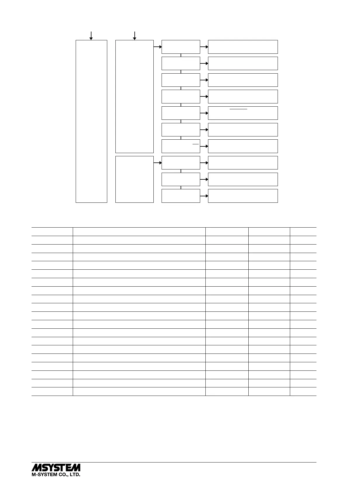
Maintenance Setting
(MAINTE)
Change Setting
(SETTINGS)
Option Setting
(OPTION)
Input line indication
(LINE)
123 (*)
RST
Phase direction
(PHASE DIR)
IND/CAP (*)
LEAD/LAG
IEC (*)
IEEE
Power factor sign
(PF SIGN)
Backup setting
(BACKUP)
NO : Cancel
YES : Backup
Reactive power sign
(QN SIGN)
IEC (*)
SPECIAL : Outgoing power sign inverted
Reactiver power calcul.
(Q CALC)
VEC S-P :
√
Sn
2
– Pn
2
(*)
SIGMA UI : Reactive power meter method
VEC P+Q (*)
S1+S2+S3
Apparent power calcul.
(S CALC)
9.999K (*)
9999
Power unit format
(P FORMAT)
Restore setting
(RESTORE)
NO : Cancel
YES : Read
Initialization
(CLEAR ALL)
NO : Cancel
YES : Initialize
(*) or ( ) : Factory setting
2.00
■ ALARM OUTPUT SETTING
ID*
1
DEFINITION
LOW SETPOINT HIGH SETPOINT UNIT
I1-3 Current, Line 1 thr. Line 3 0.000 20 000.000 A
IN Neutral current 0 20 000 A
U12-31 Delta voltage, Line 1 – 2, 2 – 3, 3 – 1 0.00 400 000.00 V
U1N-3N Phase voltage, Phase 1 thr. Phase 3 0.00 400 000.00 V
P Active power -2 000 000 000 2 000 000 000 W
Q Reactive power -2 000 000 000 2 000 000 000 var
S Apparent power 0 2 000 000 000 VA
PF Power factor -1.0000 1.0000 —
F Frequency 45.00 65.00 Hz
I1-3 AVG Average current, Line 1 thr. Line 3 (demand) 0.000 20 000.000 A
IN AVG Average neutral current (demand) 0 20 000 A
P AVG Average active power (demand) -2 000 000 000 2 000 000 000 W
Q AVG Average reactive power (demand) -2 000 000 000 2 000 000 000 var
S AVG Average apparent power (demand) 0 2 000 000 000 VA
THD I1-3 THD, Current, Line 1 thr. Line 3 0.0 999.9 %
THD IN THD, Neutral current 0.0 999.9 %
THD U12-31 THD, Delta voltage, Line 1 – 2, 2 – 3, 3 – 1 0.0 999.9 %
THD U1N-3N THD, Phase voltage, Phase 1 thr. Phase 3 0.0 999.9 %
UT12-31 Phase angle between voltages, Phase 1 – 2, 2 – 3, 3 – 1 -180 180 °
*1. Indicated while in alarm conditions.