3-2 Hardware Tuning Setup and Procedure
2.0 Hardware Tuning Setup and Procedure
2.1 Tuning Frequency
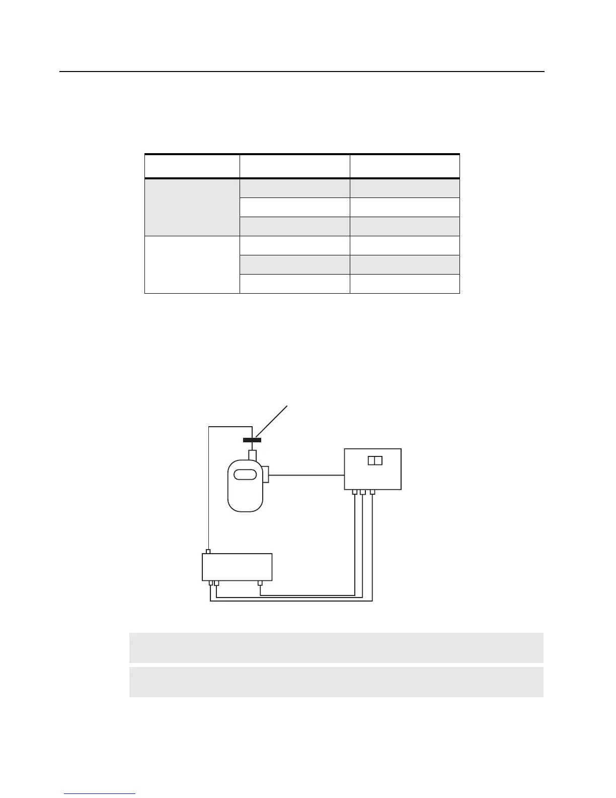
2.2 Preparation Before Tuning (refer to Figure 3-1)
1. Set Power Supply to 7.5V and then connect to the radio.
2. Connect the connector and ground plate to the radio antenna port.
3. Connect the radio to the test equipment.
Table 3-1 Frequencies Used for Tuning.
Band Tuning Parameter Frequency (MHz)
VHF 150 – 174 MHz
PLL Synthesizer 173.975
Transmitter 150.025
Receiver 150.025
UHF 450 – 470 MHz
PLL Synthesizer 469.975
Transmitter 450.025
Receiver 450.025
Figure 3-1 Radio Tuning Setup
NOTE
On the Test Box, select 8 ohm resistance when using with PMUD2086A_, and
PMUE2386A_. For all other kits, please select 24 ohm resistance.
NOTE
The radio may need to be disassembled to the PC board level to access certain tuning
ports. For disassembly, refer to
"Radio Disassembly – Detailed" on page 2-6
Ground Contact Finger
Radio
Antenna Port
Acc
Jack
TEST EQUIPMENT
N Type
BNC
Input
Lo
Hi
Tx
8 ohm 24 ohm
Rx
TEST BOX
Output
BNC
BNC BNC