Hardware Tuning Setup and Procedure 3-3
2.3 Transmitter Tuning
2.3.1 High Power
1. Connect the radio to power meter.
2. Set the radio to the appropriate tuning frequency (refer to Table 3-1).
3. Key up the radio.
4. Using the ceramic tool, adjust R425 to tune high power (refer to Figure 3-2).
2.3.2 Low Power
1. Connect the radio to power meter.
2. Set the radio to the appropriate tuning frequency (refer to Table 3-1).
3. Key up the radio.
4. Using the ceramic tool, adjust R426 to tune low power (refer to Figure 3-2).
2.3.3 Frequency Tuning
1. Set the radio to the appropriate tuning frequency (refer to Table 3-1).
2. Using the ceramic tool, adjust FL701 to tune the frequency (refer to Figure 3-2).
2.3.4 Modulation Balancing
1. Set the radio to the appropriate tuning frequency (refer to Table 3-1).
2. On the test equipment, set the following configurations:
Audio bandwidth: 0.25Hz to 15,000Hz.
De-emphasis: Off.
FM: Peak negative.
3. Using the Audio Analyzer, inject a 1 kHz tone to the radio through the test box.
4. Key up the radio.
5. Set the desired modulation balance at the output level of the Audio Analyzer.
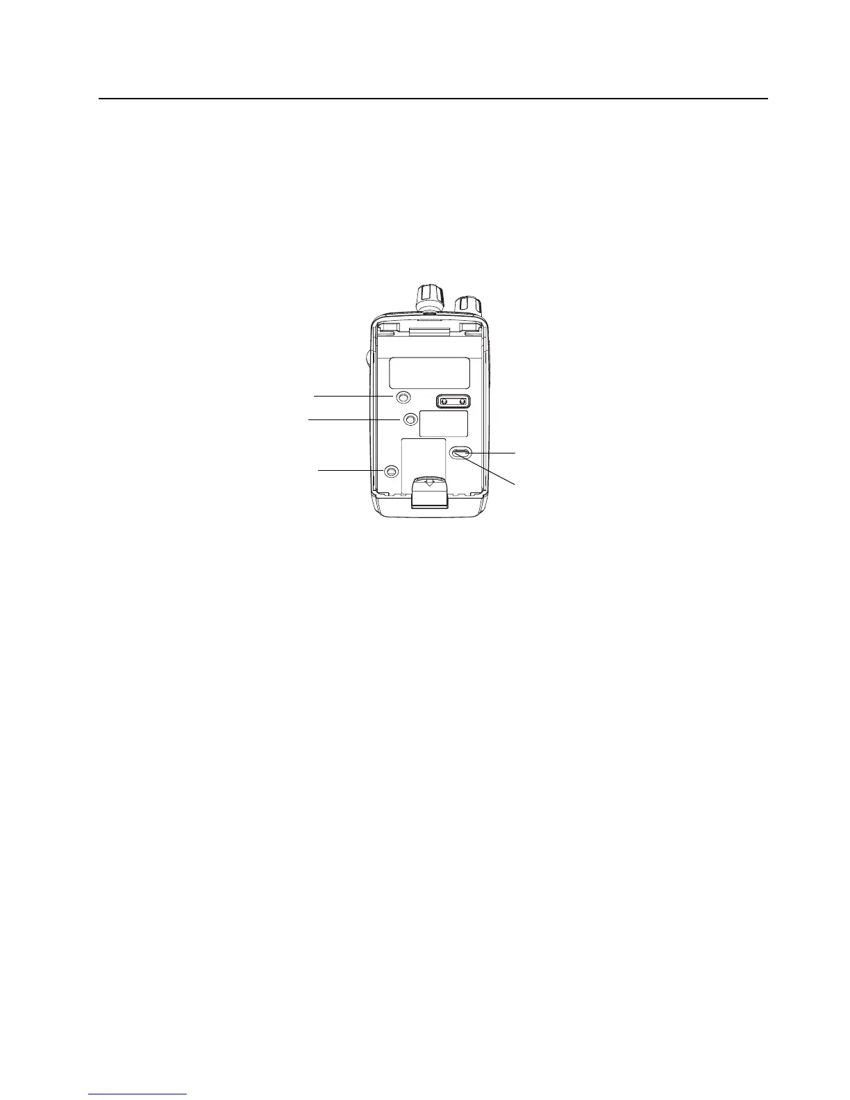
Figure 3-2 Tuning Ports
R425
R426
FL701
R216
R215