3-4 Hardware Tuning Setup and Procedure
6. Using the ceramic tool, adjust R174 to tune to 100% of the maximum deviation (refer to
Figure 3-3).
2.3.5 Maximum Modulation
1. Set the radio to the appropriate tuning frequency (refer to Table 3-1).
2. On the test equipment, set the following configurations:
Audio bandwidth: 0.25Hz to 15,000Hz
De-emphasis: Off
FM: Peak negative
3. Using the Audio Analyzer, input a 1 kHz tone + 67Hz subtone, 120mV to the radio through the
test box.
4. Key up the radio.
5. Using the ceramic tool, adjust R159 to tune maximum modulation between 2.4±0.02KHz for
narrow band or under 5KHz for wide band (refer to
Figure 3-3).
2.3.6 Subtone Modulation
1. Set the radio to the appropriate tuning frequency (refer to table3-1).
2. On the test equipment set the following configuration
Audio bandwidth: 0.25Hz to 15,000Hz
De-emphasis: Off
FM: Peak negative
3. Program radio subtone to 67Hz (CTCSS).
4. Key up the radio.
5. Using the ceramic tool, adjust R172 to tune subtone modulation between 0.42 ± 0.02KHz at
narrow band (refer to
Figure 3-3).
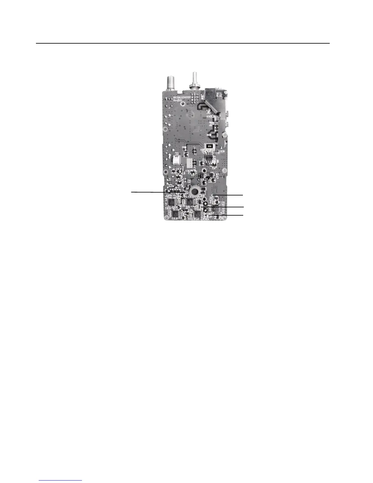
Figure 3-3 Top Side of PCB
R159
TP1
R174
R172