STANDARD CONTROL/DISPLAY OPERATION
35
Standard Control/Display Unit
Operation
General
The Standard Control/Display Unit (SCDU) is
used to change and/or monitor various drive
dependent operational set points and perform
diagnostics for the Magnetek DSD Elevator
Drive. The SCDU is located in the upper right
corner of the Drive Control PCB and is
accessible through the power cube cover.
This Control/Display Unit is present on every
Magnetek DSD 412 Elevator Drive.
The SCDU consists of a 4-button keypad, a 4-
1/2 digit numeric LED display, red and green
colored LEDs, an "NVRAM PROTECT" switch
(marked NV RAM PROTECTION on the
power cube cover), and a red LED that shows
the status of the "NVRAM PROTECT" switch.
Start-Up Operation
When power is first applied to the drive, all of
the segments on the 4-1/2-digit display will
turn on briefly in order to show that all are
functioning:
+
1. 8. 8. 8. 8.
Both LEDs Off
After this lamp test is completed, an internal
check is made to determine if the NVRAM
chips have ever been used before, or if the
EPROM’s are the same as before power
down. If not, the drive software will attempt to
load the defaults into the NVRAM chips. The
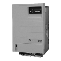
SCDU displays the word ‘Prot’ if the NV RAM
PROTECTION switch is in the position that
will not allow any updates of the NVRAM:
P r o t
If the display shows ‘Prot’, it is necessary to
move the NV RAM PROTECT switch to the
"OFF" position and press the CPU RESET
button in order to load defaults into NVRAM
and restart the drive. Then set the NV RAM
PROTECT switch back to "ON". This ‘Prot’
message will only happen when: A. The drive
is powered up for the very first time. B. If the
software in the drive is changed. C. The
NVRAM chip (U56) is changed.
After the LED lamp test has completed, the
drive software will now perform a fuse test on
each of the three line fuses. If any power
conversion fuse is open, the SCDU will
indicate this on its display. The SCDU display
is arranged in a similar manner to the physical
placement of the 3 line fuses in the power
cube. The middle segments of the three right-
most digits are used to indicate blown fuses.
For example, if the left-most line fuse is bad,
the SCDU will report it as follows:
Red LED Lit
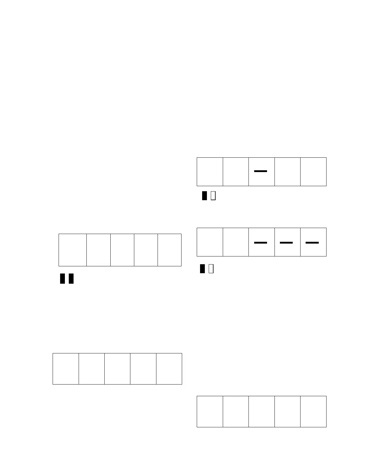
If any two or more fuses are blown, the SCDU
display will be:
Red LED Lit
The operator should then identify which fuses
have failed.
The drive will not operate unless all three line
fuses are functional. If the SCDU indicates a
bad fuse, power must be removed from the
drive, the fuse replaced and power reapplied.
After the drive has performed all three tests
(lamp test, RAM test, and fuse test), the
SCDU displays one of two final messages. If
there are any faults present at this time, the
SCDU will display a Fault code. The display
will be similar to:
F 4 0 7
 Loading...