Input / Output Verification
99
Input – Output Signal Verification
The Control Display Unit (CDU) function #981 may be used to directly read and track the status of
logic input and output signals at DSD 412 drive terminals. This is an easy way to verify the
integrity of input and output logic signals to the drive. Refer to specific connection diagrams for
your application to confirm the definition of how each signal is being used. The I/O indicator
technique as described below will work regardless of whether or not the particular terminals and
signals are used by internal software logic or actually wired into your application. Function #981
does not work with the Portable Control display Unit.
Here’s how to use this valuable troubleshooting tool:
1. Press the Up ▼ or Down ▲ keys and go to F#981.
2. Press the DATA FCTN KEY. The green light should turn ON to indicate that data is being
displayed.
3. Segments on the local Control Display Unit will light up to indicate active input and output logic
actions. Vertical segments represent input signals and horizontal segments represent output
signals as identified below.
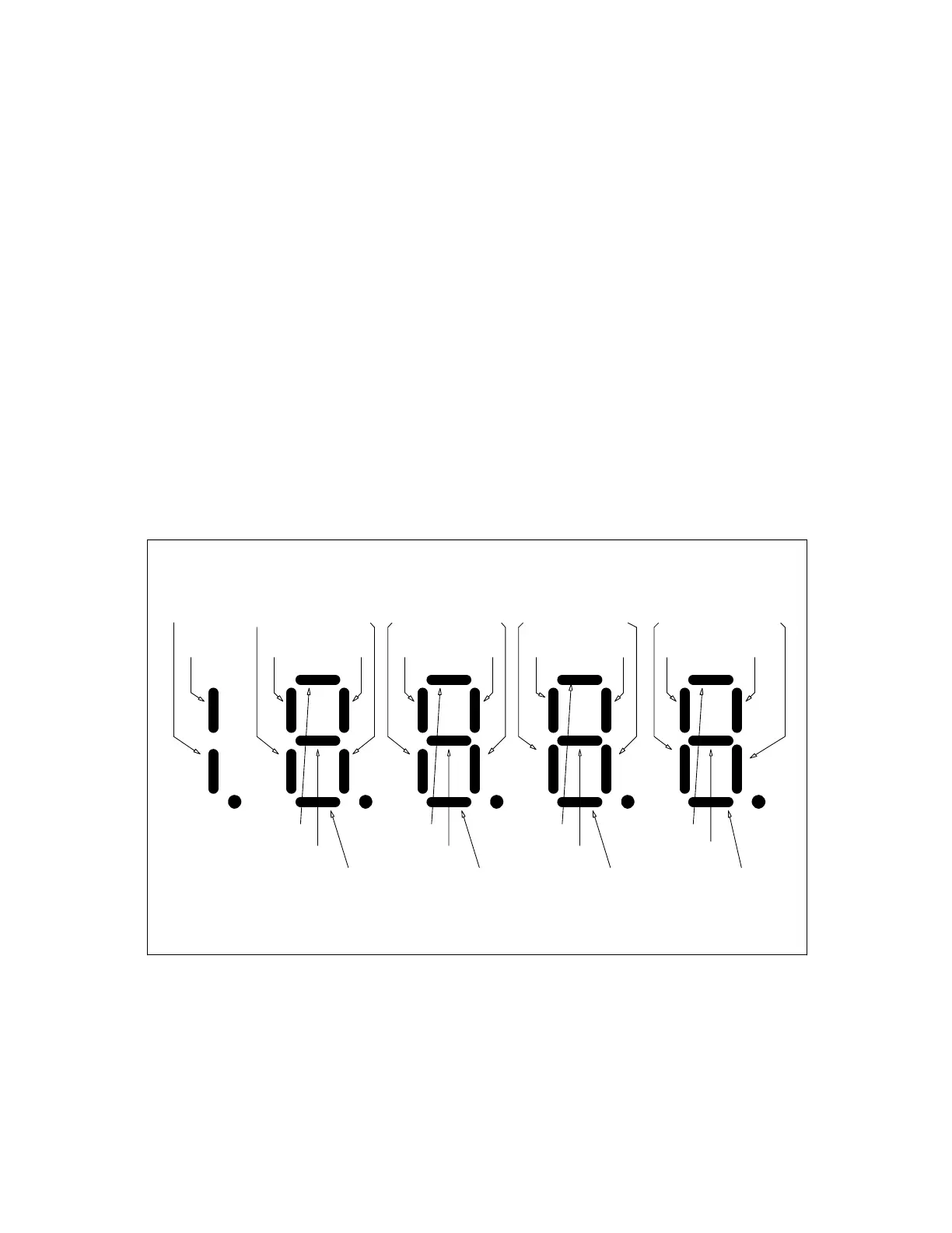
Figure 23: I/O Monitor Function
E-STOP
TB3(6)
TB1(53)
TB1(7)
TB1(12)
TB1(49)
TB1(54)
TB1(8) TB1(50) TB1(9)
THRMST
TB3(8)
TB1(51) TB1(10) TB1(11)
TB1(40,41,42)
TB1(79)
TB1(38-39)
TB1(83)
TB1(36-37)
TB1(84)
TB1(78)
LPR
TB3(5)
I N P U T L O G I C D A T A B I T S
O U T P U T L O G I C D A T A B I T S
N-A N-A N-A N-A
N-A N-A N-AN-A
TB1(52)
 Loading...