inteleSmart2 Instruction Manual
June 2016
Page 14 of 49
13. Wiring of the system should now be complete. Install antenna.
14. If there are any problems, refer to Section 9.
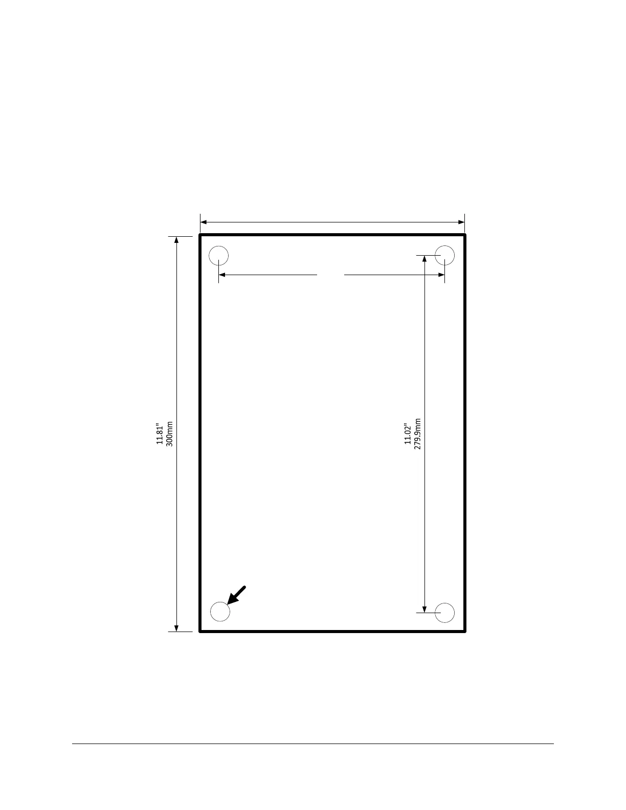
3.9 MECHANICAL DRAWINGS
The receiver housing provides four mounting holes. The mounting hardware should consist of M5 (#10-
24) combo drive round head screws that are 40mm (1.5 in) in length, four M5 (#10) lock washers, and
four M5 (#10-24) hex nuts to mount. Lock washers should be used in front of hex nuts.
7,87"
200mm
7.09"
180mm
.30"DIA.
7.5mm
Hole4places
Figure 1: Housing Mounting
NOTE: Figure 1 is not to scale.