
D
Darius AndersonSep 10, 2025
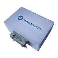
Why is there no response from the IR connection on my Magnetek inteleSmart2?
- Wwyatt62Sep 10, 2025
If there is no response from the IR connection on the Magnetek receiver, make sure the IR adapter has line of sight with the IR eye in the unit.