inteleSmart2 Instruction Manual
June 2016
Page 23 of 49
6. INTELESMART2 EXPANSION MODULE TYPES
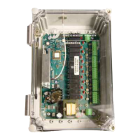
The inteleSmart2 system consists of a CPU board that contains fourteen base relays, two machine stop
relays, power supply, RF, one analog input, five digital inputs, IR, CAN, and USB. There is support to
add up to two different expansion modules.
The expansion modules should be placed in J9 (expansion module 1) and J10 (expansion module 2) on
the main board (Figure 2). To get the main board to allocate the correct parameters for each of the
expansion modules, power the system off to put the boards in. When the system is powered back on,
the software on the main board will automatically detect what type of expansion module has been
inserted and make the appropriate calls to initialize the expansion module.
It is possible to place an expansion module in slot 2 (J10) without a module in slot 1 (J9) and have the
system operate correctly. If the system is set up to drive I/O on an expansion module that is not present,
the system will show an error.
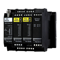
6.1 RELAY EXPANSION MODULE
The relay expansion module allows eight normally open relays to be added to the inteleSmart2 system.
Each relay has an individual input associated with it. When wiring to the relay expansion module, ensure
that the correct expansion module is being wired to in order to avoid incorrect motions from being
activated. Figure 5 shows the wiring diagrams for the relay expansion modules for expansion module 1
and expansion module 2.