EasyManua.ls Logo

Magnetek Flex M User Manual

Magnetek Flex M
50 pages
To Next Page IconTo Next Page
Page #1 background imageLoading...
Page #1 background image
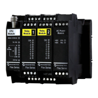
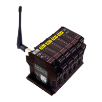
Flex M RECEIVER
Engineered
Modular Receiver
Part Number: 198-80104-1100 R05
May 2019
© 2019 Magnetek

Questions and Answers:

Magnetek Flex M Specifications

General IconGeneral
BrandMagnetek
ModelFlex M
CategoryReceiver
LanguageEnglish

Summary

Service Information and Contacts

U.S. Service Information

Contact details for US technical and service inquiries.

World Headquarters

Magnetek's main office contact information and address.

Canada Service Information

Contact details for Canadian service and technical support.

EU Market Contact

Contact information for the EU market representative.

Product Safety Information

Warranty Information

Details on product warranties and where to find them.

Warnings and Cautions

Critical Installation Considerations

General Operation Guidelines

Overview of radio-controlled equipment operation.

Authorized Operators

Criteria for personnel permitted to operate equipment.

Operator Safety and Training Requirements

Essential knowledge and skills for operators.

Pre-Operation Test Procedure

Steps to perform before operating equipment.

Flex M Installation Procedures

Environmental Considerations

Operating temperature and humidity limits for the receiver.

Pre-Installation Checks

System checks before commencing installation.

Receiver Mounting Location

Guidelines for choosing the optimal mounting spot.

Antenna Mounting Guidance

Recommendations for optimal antenna placement.

Line Input Considerations

Requirements for power line connections.

Wiring Best Practices

Rules and recommendations for electrical wiring.

Receiver Unit Enclosure Mounting

How to mount the receiver unit within an enclosure.

Receiver Installation Steps

Step-by-step guide for installing the receiver.

Module Removal Procedure

Instructions on how to detach modules from the rail.

Mechanical Drawings

Flex M System Modules

RF/CPU Module - Gen 1

Description and part numbers for the first generation RF/CPU module.

RF/CPU LED Operation (Gen 1)

Explanation of status LEDs for Gen 1 RF/CPU module.

RF/CPU Module - Gen 2

Description and part numbers for the second generation RF/CPU module.

RF/CPU LED Operation (Gen 2)

Explanation of status LEDs for Gen 2 RF/CPU module.

Power Supply Module - Gen 1

Description and part numbers for Gen 1 power supply.

Power Supply LED Operation (Gen 1)

Explanation of status LEDs for Gen 1 power supply.

Power Supply Module - Gen 2

Description and part numbers for Gen 2 power supply.

Power Supply LED Operation (Gen 2)

Explanation of status LEDs for Gen 2 power supply.

Relay Module - Gen 1

Description and part numbers for Gen 1 relay module.

Relay Module LED Operation (Gen 1)

Explanation of status LEDs for Gen 1 relay module.

Relay Module - Gen 2

Description and part numbers for Gen 2 relay module.

Relay Module LED Operation (Gen 2)

Explanation of status LEDs for Gen 2 relay module.

Serial Communication Module

Details of the serial communication module.

Serial Communication LED Operation

Explanation of status LEDs for serial module.

Analog I/O Module

Description of the analog input/output module.

Analog I/O LED Operation

Explanation of status LEDs for analog I/O module.

Digital Input Module - Gen 1

Description and part numbers for Gen 1 digital input module.

Digital Input LED Operation (Gen 1)

Explanation of status LEDs for Gen 1 digital input module.

Digital Input Module - Gen 2

Description and part numbers for Gen 2 digital input module.

Digital Input LED Operation (Gen 2)

Explanation of status LEDs for Gen 2 digital input module.

Programming with RCP Software

Receiver Channel Configuration

FCC Compliance Statements

Regulatory statements required by the FCC.

Gen 1 RF/CPU DIP Switch Settings

Channel Sets

433MHz Channel Set

List of available channels and their frequencies for 433MHz.

419MHz Channel Set

List of available channels and their frequencies for 419MHz.

2.4 GHz FHSS Channel Set

Description of 2.4 GHz frequency hopping channels.

Troubleshooting Guide

Troubleshooting Table

Common problems, reasons, and suggested solutions.

EU Declaration of Conformity

Related product manuals