Flex M Engineered Receiver Instruction Manual
May 2019
Page 19 of 50
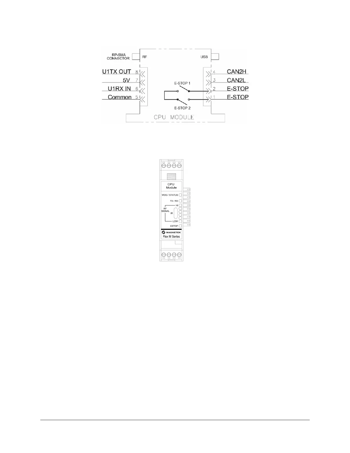
Figure 8. GEN2 RF/CPU Module Wiring
4.2.1 RF/CPU LED OPERATION
When the Flex M system supplies power to the RF/CPU module, there is a series of LEDs that indicate
the RF/CPU module’s status.
Figure 9. GEN2 RF/CPU Module LED Placement
• WDG/ONLINE LED:
o 1 Green Blink indicates normal operating WDG
o 2 Amber Blinks indicates RF communication loss with transmitter or when the transmitter
is powered off
o 3 Amber Blinks indicates a read/write error to an attached Flex M module
o 6 Amber Blinks indicates that the machine stop has been pressed or that there is an
internal machine stop error
• RF MSG LED:
o Green Blinks indicates radio frequency messages received. This confirms
communication between transmitter and receiver.
• RF SIGNAL LEDs:
o Indicates the strength of the RF communication signal from the transmitter. A weak signal
is indicated by only the red LEDs illuminated. As the signal strength increases, amber
and then green LEDs will light. Green LEDs indicate a strong signal.
• E-STOP LED
o Bicolor LED. Yellow indicator when K1 Relay is active. Green indicator when K2 Relay is
active