Flex M Engineered Receiver Instruction Manual
May 2019
Page 27 of 50
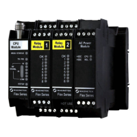
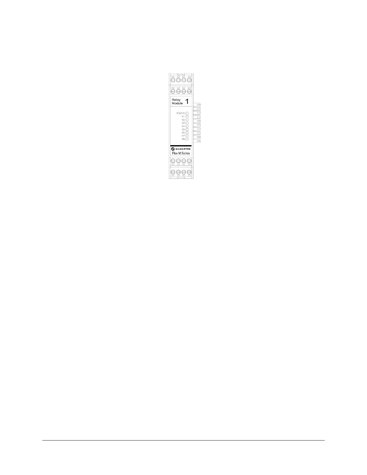
4.6.1 RELAY MODULE LED OPERATION
When the Flex M system is supplying power to the Relay module, an LED indicates the power and
communication status of the Relay module.
Figure 23. GEN2 Relay Module LED Placement
• OK LED
o Solid indicates module communication with system is good
o 3 Blinks indicates read/write error to attached CPU module
Additionally, there are eight LEDs labeled 1 through 8 on the Relay module. When the LED is on, this
indicates that the relay is activated.
4.7 SERIAL COMMUNICATION MODULE
This section is applicable to the following serial communication part number(s):
• 25-02-074-809E
The Flex M Serial Communication module allows the communication via RS-232 (2-wire only), RS-422 (4-
wire only), or RS-485 (4-wire only). Any of these interfaces can operate in full duplex, while only RS-232
supports half-duplex operation. When operating in full duplex with RS-422 and RS-485, the
communication module must always be the master. The communication module can only operate as a
slave in half-duplex mode.
The Serial Communication module also support CAN-BUS 2.0B.
The Serial Communications module number is set by the rotary switch located on the lower left corner of
the board.