Flex M Engineered Receiver Instruction Manual
May 2019
Page 29 of 50
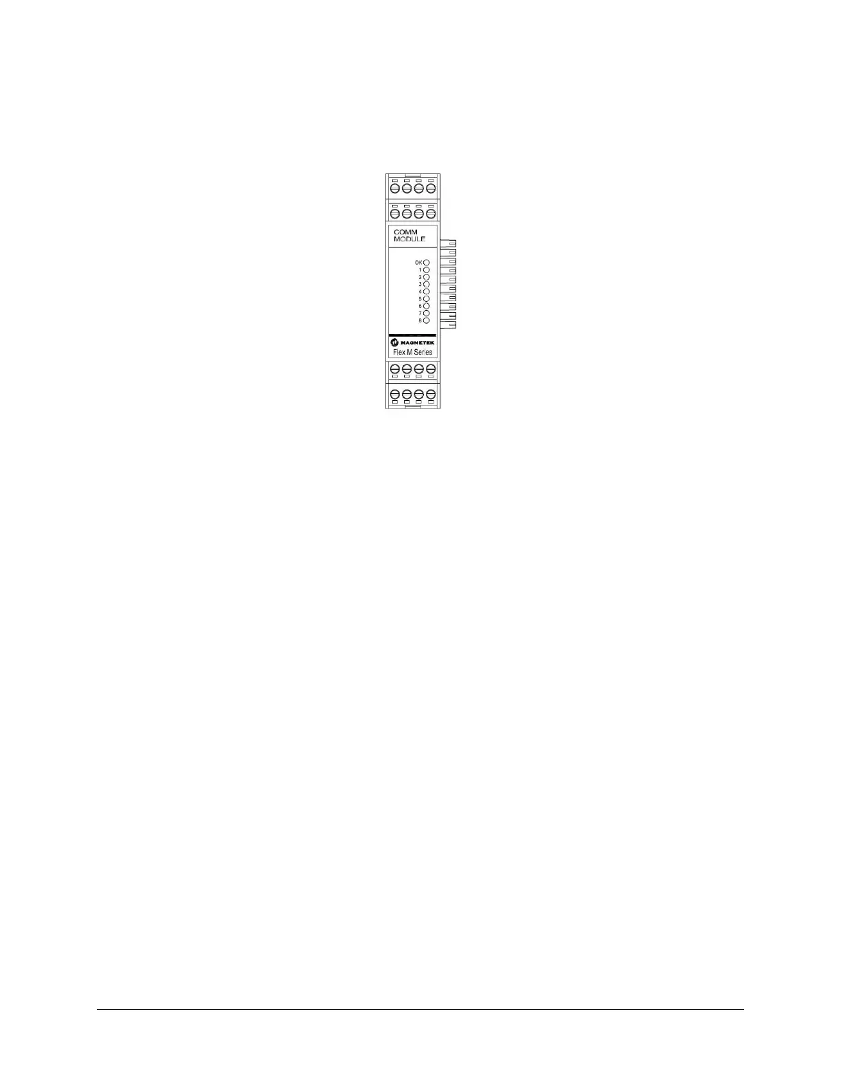
4.7.1 SERIAL COMMUNICATION MODULE LED OPERATION
When the Flex M system is supplying power to the Serial Communication module, an LED indicates the
power and communication status of the Serial Communication module.
Figure 26. Serial Communications Module LED Placement
• OK LED
o Solid indicates module communication with system is good
o 3 Blinks indicates read/write error to attached CPU module
Additionally, there are eight LEDs labeled 1 through 8 on the Serial Communication module.
• When LED number 1 is steady, this indicates an internal CAN bus initialization error.
• When LED number 2 is steady, this indicates an external CAN bus initialization error.
• When LED number 2 is blinking, this indicates message reception on the external CAN bus.
• When LED number 3 is blinking, this indicates that the Serial Communication Card is
communicating with the attached drive. This is only applicable for RDSI systems.
• When LED number 5 is on steady, this indicates there is a serial communication time-out error
(the serial communication was inactive for 1 second). See Section 9 for additional information.
• When LED number 6 is on steady, this indicates that the Serial Communication is in test mode.
• When LED number 7 is on steady, this indicates that the CPU module is sending a drive forward
command. This is only applicable for RDSI systems.
• When LED number 8 is on steady, this indicates that the CPU module is sending a drive reverse
command. This is only applicable for RDSI systems.
4.8 ANALOG I/O MODULE
This section is applicable to the following analog I/O part number(s):
• 25-02-074-806E
Outputs:
The four analog output signals are able to send voltage signals from 0 to +/-10VDC, at an 8-bit resolution.
These outputs are for reference voltage only, so each one can only supply 20mA of current. The outputs
share a common ground reference, which is isolated from the Flex M system ground and any additional
I/O card output ground. These outputs can be preconfigured at the factory for different voltage ranges
(ex. 0-5VDC, or 3-6-9VDC).