Flex M Engineered Receiver Instruction Manual
May 2019
Page 23 of 50
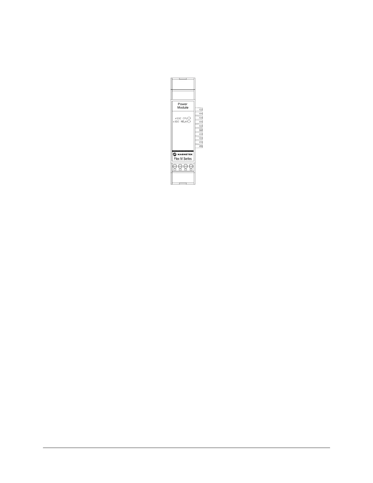
4.4.1 POWER SUPPLY LED OPERATION
When the Flex M system has power supplied, the two LEDs on the power supply module should be lit and
solid.
Figure 17. GEN2 Power Supply Module LED Placement
• +5VDC CPU
o Indicates that +5VDC power is going to the CPU
• +5VDC RELAY
o Indicates that +5VDC power is going to the RELAY modules
4.5 RELAY MODULE – GEN 1
This section is applicable to the following relay module part number(s):
• 25-02-074-805E
Identifying a GEN1 Relay module:
• The module will contain a label with the part number listed above
• The LED overlay decal will be black
The Flex M Relay module allows the control of high current power (up to 5A) for attached equipment
through eight relay outputs. Four relays have a common power input and four relays have individually
separate power inputs. The rotary switch located on the lower left corner of the board sets the relay
module number.
Relays are rated for 10 Amps 277VAC/30VDC, 1 HP 240VAC, but fused for 5A. External suppression for
the relays is needed.