Flex M Engineered Receiver Instruction Manual
May 2019
Page 17 of 50
4.1.1 RF/CPU LED OPERATION
When the Flex M system supplies power to the RF/CPU module, there is a series of LEDs that indicate
the RF/CPU module’s status.
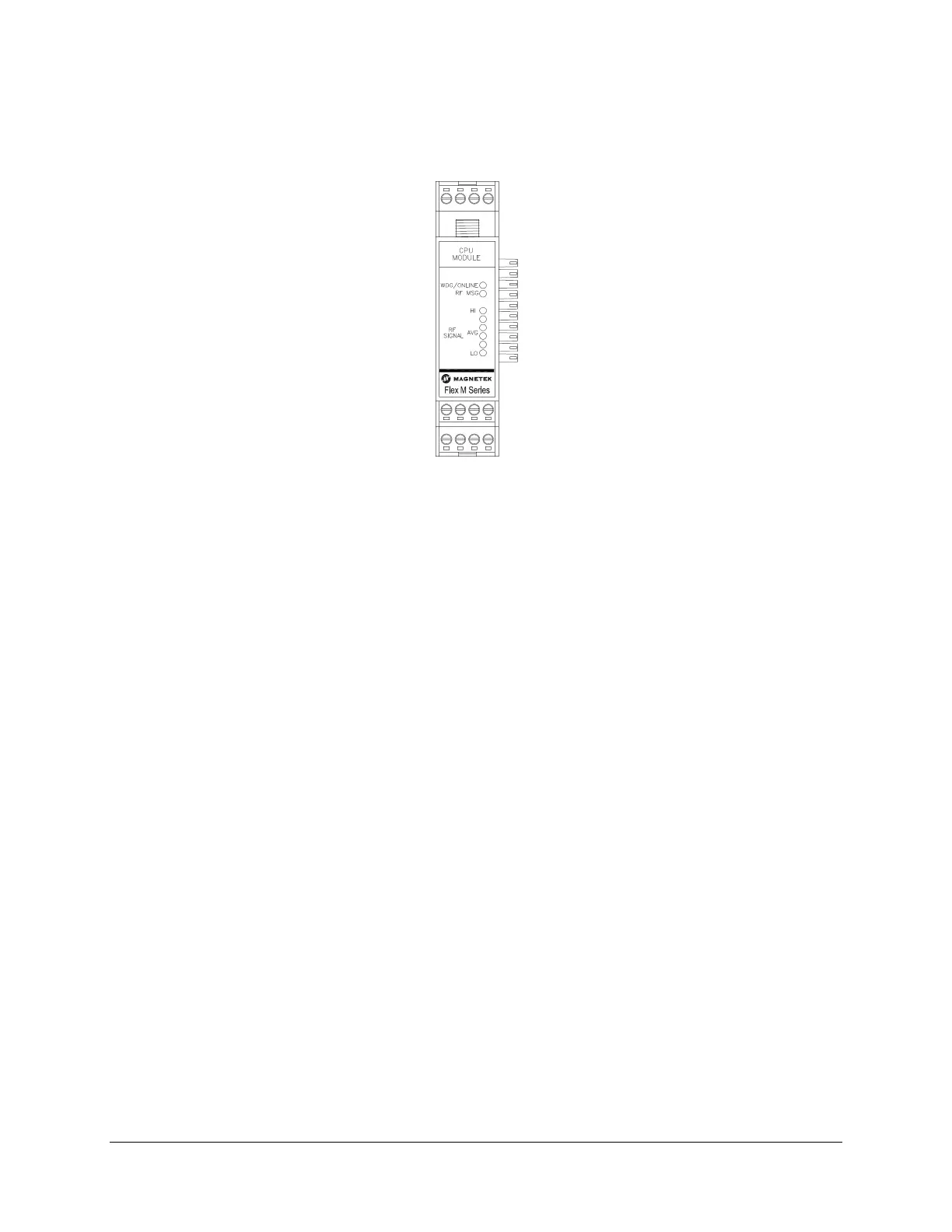
Figure 6. GEN1 RF/CPU Module LED Placement
• WDG/ONLINE LED:
o Solid indicates RF communication with transmitter
o 1 Blink indicates normal operating WDG
o 2 Blinks indicates RF communication loss with transmitter
• RF MSG LED:
o Fast Blinks indicates radio frequency messages received (typical frequency is 4 to 10
messages per second). This confirms communication between transmitter and receiver
o 3 Steady Blinks indicates read/write error to an attached Flex M module
o 4 Steady Blinks indicates an internal radio error
• RF SIGNAL LEDs
o Measures the strength of the RF communication signal from the transmitter