Flex M Engineered Receiver Instruction Manual
May 2019
Page 33 of 50
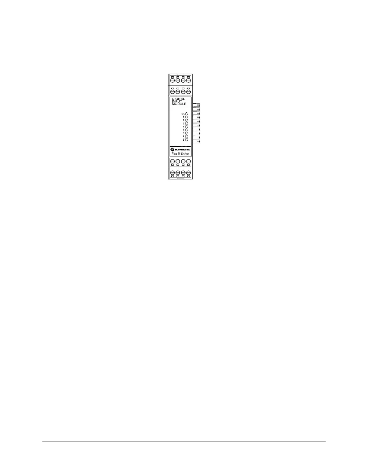
4.9.1 DIGITAL INPUT MODULE LED OPERATION
When the Flex M system is supplying power to the Digital Input module, an LED indicates the power and
communication status of the Relay module.
Figure 32. GEN1 Digital Input Module LED Placement
• OK LED
o Solid indicates module communication with system is good
o 3 Blinks indicates read/write error to attached CPU module
Additionally, there are eight LEDs labeled 1 through 8 on the Digital Input module. When the LED is on,
this indicates that the module is receiving a signal/input at that input.
• LED1
o Digital Input 1 is active (non-zero)
• LED2
o Digital Input 2 is active (non-zero)
• LED3
o Digital Input 3 is active (non-zero)
• LED4
o Digital Input 4 is active (non-zero)
• LED5
o Digital Input 5 is active (non-zero)
• LED6
o Digital Input 6 is active (non-zero)
• LED7
o Digital Input 7 is active (non-zero)
• LED8
o Digital Input 8 is active (non-zero)
Inputs 9 through 12 do not have a viewable LED.