51-604 Echotel Model 910
5
2.5.2 Relay
Model 910 switches have a number of possible relay
wiring options. The table below lists the relay contact
positions for all possible combinations of power failure,
condition of the transducer gap, and fail-safe jumper
position. The user must decide which combinations
constitute fail-safe and alarm conditions, and then select
the appropriate relay wiring and fail-safe position.
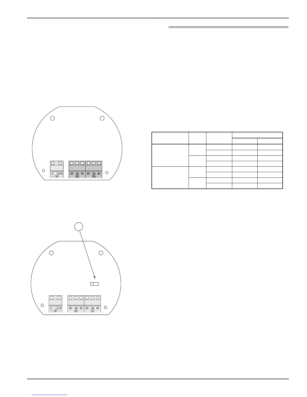
1. Run relay output wiring to the terminal blocks labeled
TB2 and TB3. Ensure that the load to be controlled is
within the relay’s rated capacity as shown in Section 3.3.2,
Electrical on page 6.
2. Select high or low fail-safe using the P1 jumper.
3. Replace housing cover. Installation is complete.
Caution: Never tighten unit to the tank connection by turning the
housing. Use a wrench on the transducer mounting nut
flats. Use thread tape or suitable pipe compound on
threads. Do not over tighten.
P1 Fail-safe Line Transducer
Relay Terminals
Jumper Position Power Gap
CM to NC CM to NO
On
Dry Closed Open
Low level
Wet Open Closed
Failure
Dry Closed Open
Wet Closed Open
On
Dry Open Closed
High level
Wet Closed Open
Failure
Dry Closed Open
Wet Closed Open




 To Next Page