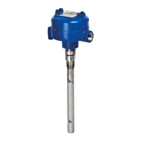
BE 57-658 Eclipse
®
Model 706 Guided Wave Radar Transmitter – PROFIBUS PA output
Table of Contents
1.0 PROFIBUS PA Overview
1.1 Description ...............................................................4
1.2 Benefits .....................................................................5
1.3 Device Configuration................................................5
1.3.1 PROFIBUS DD Revision Table......................6
1.4 Intrinsic Safety ..........................................................7
2.0 Function Blocks
2.1 Overview...................................................................7
2.1.1 Standard PROFIBUS Block Parameters ...........8
2.2 Physical Block ...........................................................8
2.3 Analog Input Block.................................................10
2.3.1 AI Block Parameters .....................................10
2.3.2 Local Display of
Analog Block Output Values ........................11
2.3.2.1 AI Out Display Screens .........................12
2.3.3 AI Block Configuration................................13
2.4 GWR Transducer Block ..........................................14
3.0 Model 706 Transmitter Configuration
3.1 Configuration Information .....................................14
3.2 Menu Transversal and Data Entry...........................15
3.2.1 Navigating the Menu ...................................15
3.2.2 Data Selection ..............................................16
3.2.3 Entering Numeric Data Using Digit Entry ..16
3.2.4 Entering Numeric Data Using
Increment/Decrement ..................................17
3.2.5 Enter Character Data ...................................17
3.3 Password Protection ................................................18
3.4 Model 706 Menu: Step-By-Step Procedure .............19
3.5 Model 706 Configuration Menu: Device Setup ......21
4.0 Troubleshooting and Diagnostics
4.1 Diagnostic Parameters .............................................27
4.1.1 Diagnostics (Namur NE 107) ......................28
4.1.2 Diagnostic Indication Simulation.................29
4.1.3 Diagnostic Indicator Table ...........................29
4.1.4 Diagnostic Help ...........................................32
4.2 Diagnostic Parameters.............................................33
4.3 PROFIBUS PA Segment Checklist .........................36
Appendix A .........................................................................37
Eclipse
®
Model 706 GWR transmitter
with PROFIBUS PA Output
3
 Loading...