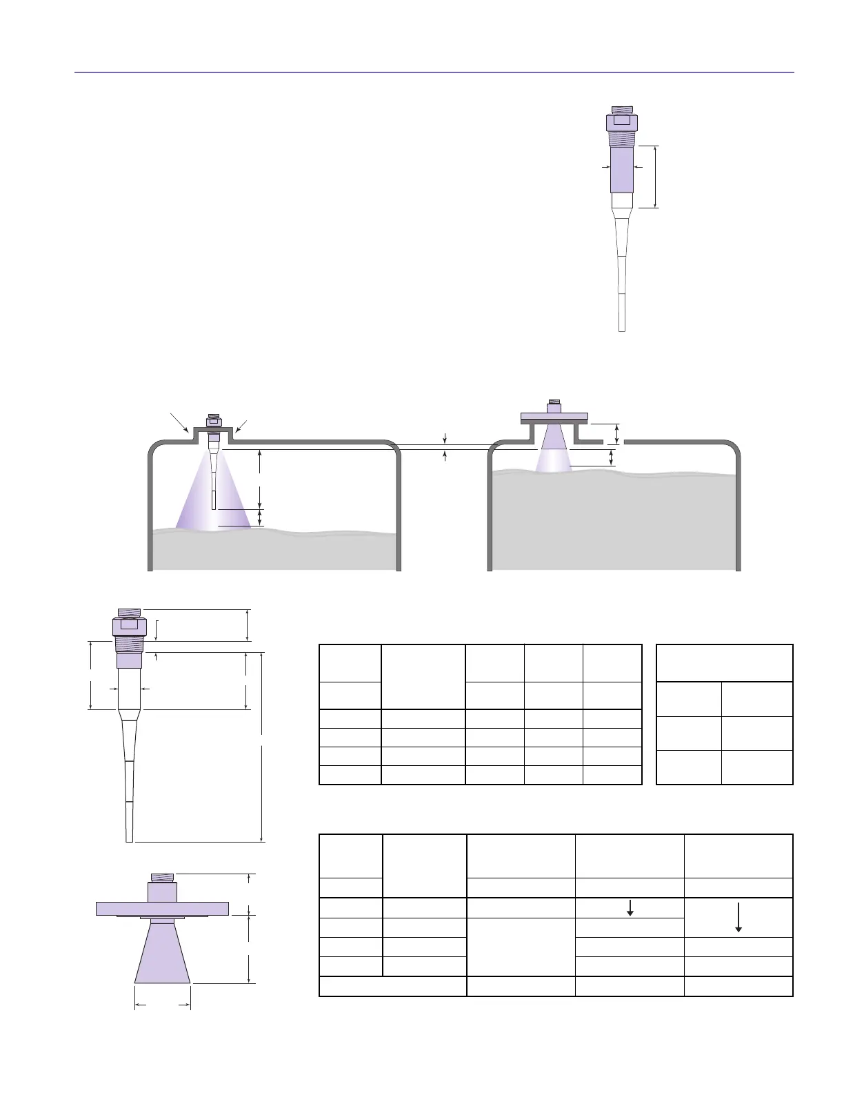
N O Z Z L E S
Improper installation in a nozzle creates “ringing” (undesired
signals) which will adversely affect measurement. The antenna
should always be mounted so the active section of the antenna
is a minimum of 0.5" (12 mm) below the nozzle. Be sure to
include any nozzle dimension inside the vessel. Refer to Figure
10. Antenna extensions are offered to allow the PULSAR Model
R96 transmitter to work reliably in nozzles with “L” dimensions
of 1" (25 mm), 4" (100 mm), 8" (200 mm) or 12" (300 mm).
Standard antennas are shown below for reference.
M O U N T I N G
5
2.8
(55)
0.68 (17) Thread
Engagement
A
C
B
D∅
Model #
Antenna
Extension
(maximum “L”
dimension)
All All BSP
8th Digit Dim A Dim B Dim C
0 1 (25) 2.2 (56) 11.1 (282) 3.0 (76)
1 4 (100) 5.1 (130) 14.0 (356) 5.9 (150)
2 8 (200) 9.1 (231) 18.0 (457) 9.9 (251)
3 12 (300) 13.1 (333) 22.0 (559) 13.9 (353)
Antenna Extension O.D.
Dimension D
TFE Rod
∅ 1.625 (41)
PP Rod
∅ 1.50 (38)
All-Plastic
Rod
∅ 1.625 (41)
Model #
Antenna
Extension
(maximum “L”
dimension)
3" Horn 4" Horn 6" Horn
8th Digit Dim H Dim H Dim H
0 1 (25)
2.7 (51)
1 4 (100)
N/A
4.6 (117)
2 8 (200) 8.4 (213) 8.3 (211)
3 12 (300) 12.4 (315) 12.4 (315)
Aperture 2.95 (75 mm) 3.75 (95) 5.75 (146)
DIELECTRIC RODS – inches (mm)
HORNS – inches (mm)
0.50" (13 mm)
Minimum
2" (50 mm)
Minimum Diameter
Dielectric Rod Antenna
C
oupling
2" (50 mm)
2" (50 mm)
8" (200 mm)
Horn Antenna
" L " Dimension (Nozzle Height)
Figure 10

 Loading...