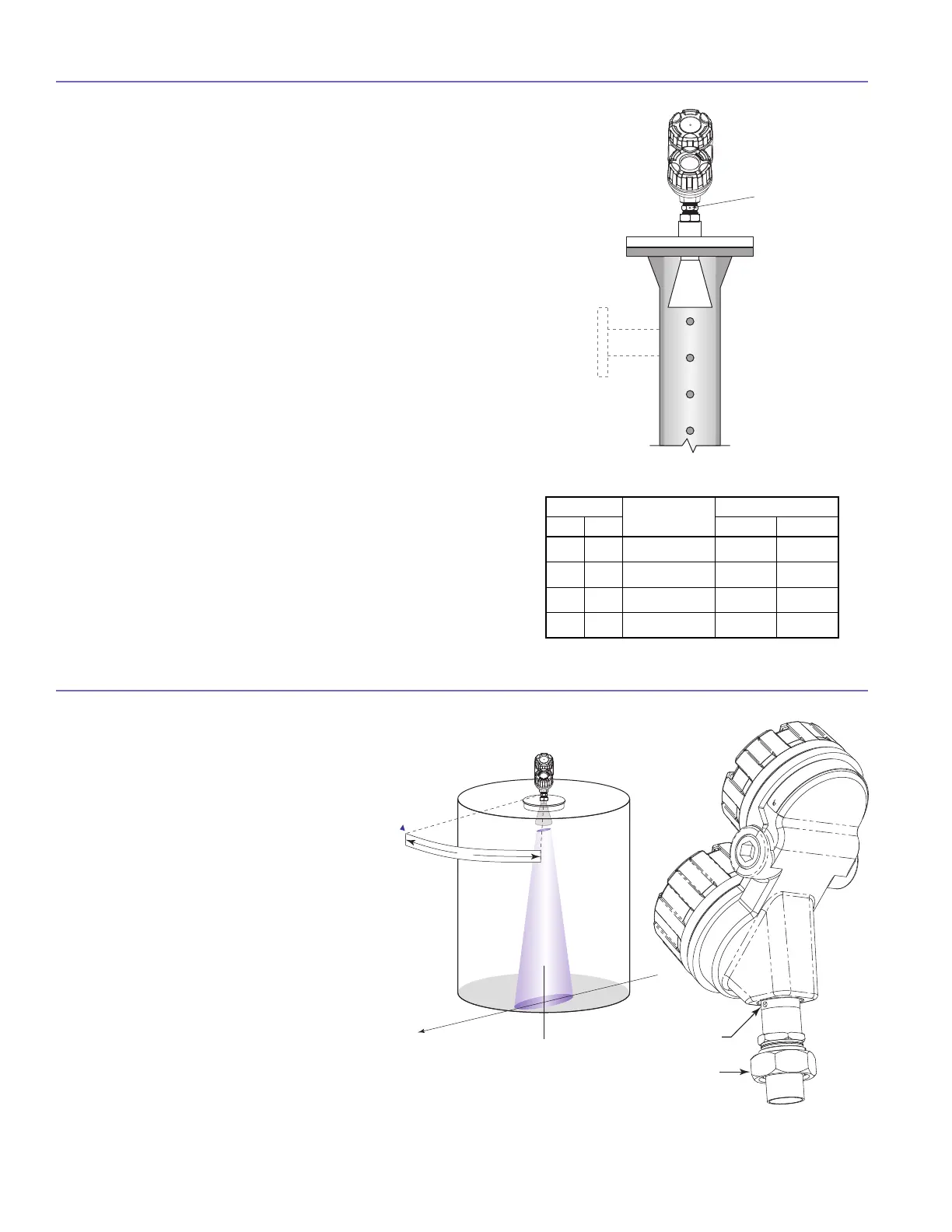
O R I E N T A T I O N
The PULSAR Model R96 transmitter utilizes a
linearly polarized, microwave beam that can
be rotated to improve its performance. Proper
orientation can minimize unwanted target
reflections, decrease sidewall reflections (multi-
path) and maximize direct reflections from the
liquid surface. The index mark located on the
side of the launcher is oriented in the same
direction as the polarization. 45° is initially
recommended. Refer to Figure 12.
The index mark is also present for reference
(1 dot: GP/IS or 2 dots: XP). The launcher is
considered to be at 0° when the index mark
is closest to the tank wall.
T
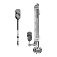
he PULSAR Model R96 can be mounted in a standpipe or
s
tillwell but certain items must be considered:
• Metal stillwells only: Sizes 3–8 inches (80–200 mm).
• Diameter must be consistent throughout length; no
reducers.
• Use only horn antennas sized to pipe ID; 3–6"
(80–150mm); 8" pipe can use a 6" horn.
• Stillwell length must cover complete range of measure-
ment (i.e., liquid must be in stillwell).
• Welds should be smooth.
• Vents: holes <0.5" diameter, slots <0.5" width.
• If an isolation valve is used, it must be a full port ball
valve with an I.D. equal to the pipe diameter.
• Bridles/Bypass Installations: The launcher (index mark)
should be rotated 90° from process connections.
• Configuration must include a non-zero entry for PIPE I.D.
• There will be some increased dielectric sensitivity;
system GAIN will be reduced when PIPE ID >0.
• There will be a slight reduction in Maximum Range
based on the table at right.
Figure 12
S T A N D P I P E S A N D S T I L L W E L L S
6
Set Screw
Universal
Connector
PIPE I.D.
Propagation
Speed Factor
Maximum Range
inch mm feet meters
3 80 0.915 60.0 18.3
4 100 0.955 62.7 19.1
6 150 0.98 64.3 19.6
8 200 0.99 65.0 19.8
Maximum Range
Figure 11
M O U N T I N G

 Loading...