Magstim Rapid²
Operating Manual
© The Magstim Company Limited 16 MOP03-EN-03
3.3.1.5 Touch-Sensitive Screen/ System Display * (5)
All selections are made via the touch-screen. To select, touch the centre of the button symbol next to
the desired menu option. Do not press hard, or use a sharp or pointed object to make the selection,
as this may damage the touch screen.
In the set-up screens, all selectable items are coloured in pale blue; white items are non-selectable.
The Rotary Control Knob can only be used to change parameters already selected. Details regarding
the contents and operation of the UI Screens are given in Sections 4.4
Note: If the UI is not used for 30 minutes it will go into a standby condition. In standby, the screen will
appear blank and the blue LED in the upper right corner of the front bezel will pulse. Touch the screen
to restore the UI.
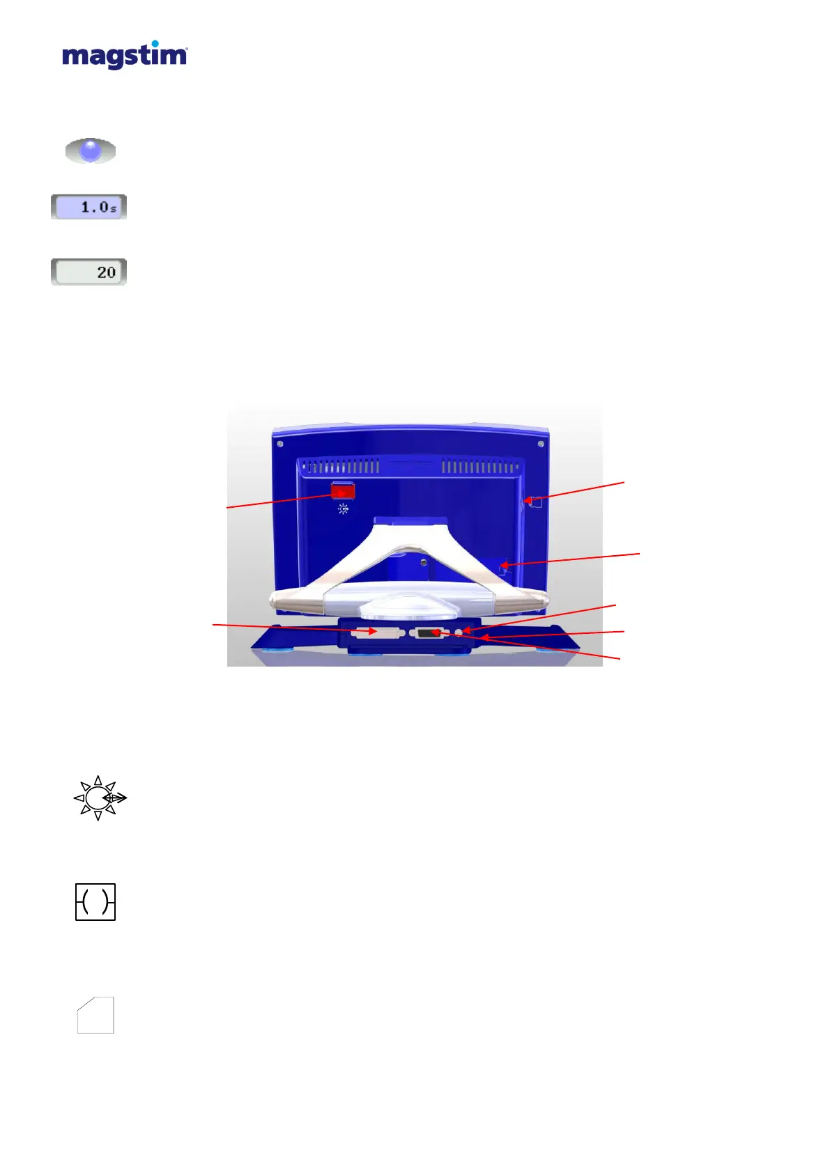
3.3.2 Rear view
Figure 3.10: Detailed front panel of Rapid² UI.
3.3.2.1 Printer Connection* (1)
The Printer is attached to the User Interface via an Optical/RS232 Interface Cable which slides into
place on the right hand side at the rear of the UI.
3.3.2.2 25 Way D-Type Connector* (2)
This connector is situated on the rear of the UI, and has 2 rows of pins. The connector links the UI to
the Magstim Rapid
2
as shown in figures 3.4 and 3.8.
3.3.2.3 SD Card Insertion Point* (3)
This socket is situated on the rear of the left hand side panel of the UI. This allows connection of an
SD Card. This removable memory storage facility enables transfer of data between the UI and
external devices, such as PCs.
 Loading...