Magstim Rapid²
Operating Manual
© The Magstim Company Limited 57 MOP03-EN-03
APPENDIX B – TRIGGER INPUT / OUTPUT
The Isolated Interface on the rear of the Magstim Rapid² stimulator and Rapid² UI allow external equipment to be
connected to enable synchronisation with an external device.
Connection to the rear of the stimulator must be made via the Stimulator Interface Module P/N 3901-00.
Voltage levels for the signals are as specified in Section 6.2.
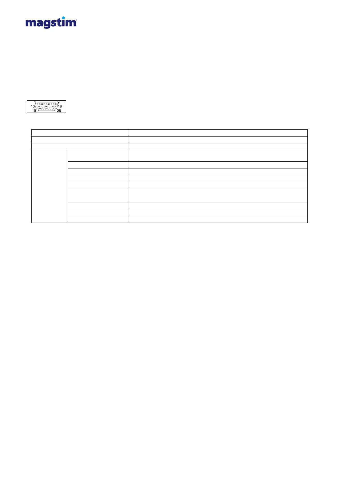
The Isolated Interface is a 26 Way High Density D-Type Female Connector.
The following tables detail the interface pins:
Rear of Stimulator and rear of Rapid² UI
Pin 3 – will be connected to Aux. Gnd. when the system is triggered.
(Open collector output, maximum external pull up voltage +5V, maximum sink current 50mA )
Pin 5 – will trigger the system when a logic high is applied.
Pin 6 – will trigger the system when a logic low is applied.
Pin 7 – a logic high will be visible when the system is triggered.
Pin 8 – a logic low will be visible when the system is triggered.
Pin 24 – unconnected sets to an edge trigger
connected to Aux. Gnd. provides a level trigger.
Trigger Edge / Level
When set to edge trigger, the Magstim Rapid² will only be triggered when the logic level being applied on the Tin+
or Tin- pin is changed. On the Tin+ pin, triggering will occur when the logic level is changed from low to high. On
the Tin- pin, triggering will occur when the logic level is changed from high to low. Edge triggering will only allow
one trigger per logic level change.
When set to level trigger, the Magstim Rapid² will be triggered when the appropriate logic level is applied to the
Tin+ or Tin- pins. On the Tin+ pin, a logic high will need to be applied. On the Tin- pin, a logic low will need to be
applied. The system re-fire when the system is ready until the logic state being applied changes or is removed.
Note: For the Tin trigger pulse to fire the system, it need to be in an armed state when the trigger is applied and
another trigger will need to be applied i.e. coil switch.
Tout O/C
Tout O/C is connected to an open collector device inside the Magstim Rapid² meaning a pulled up resistor is
required to use this feature.
Please Note: Only equipment that meets the relevant IEC standard should be connected to the Magstim Rapid²*.
This connection must be configured in compliance with Clause 16 of IEC 60601-1:2005 with the following interface
voltage limitation: Max signalling voltage +5.3V; Max voltage with respect to protective earth potential 30V peak