Magstim Rapid²
Operating Manual
© The Magstim Company Limited 21 MOP03-EN-03
6. Connect the UI Controller to the Magstim Rapid² Main Frame via the UI cable supplied.
7. If a foot switch is to be used, insert the pneumatic connector of the foot switch to the rear panel
Foot Switch Socket on the mainframe*.
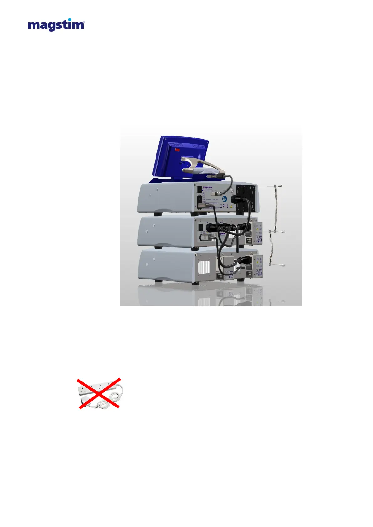
8. Attach the earth straps provided as illustrated in figure 4.3.
Standard Rapid² & Super Rapid²: Single earth strap between main frame and PSU.
Rapid² Plus²: Two earth straps, one between the main frame and the plus¹, the second between
the Plus¹ and the PSU.
Figure 4.3: Attaching the earth strap
9. Connect the power cables provided to the power supply socket(s) on the rear of the PSU (and
Plus¹ when in Rapid² Plus¹ configuration). The power requirement of the Magstim Rapid2
depends on the PSU used and the parameters set by the UI.
Standard Rapid²: A single power lead connected to the PSU.
Super Rapid²: Two power leads connected to the PSU.
Rapid² Plus²: Three power leads. Two connected to the PSU and one connected to the Plus¹.
Note: The power cables must be connected directly to wall power outlet
sockets, and not via a terminal block. The Rapid
2
System must be used only
with the supplied mains leads fitted with an integral filter, as they are required
to maintain the System’s compliance with EN 60601-1-2 regarding Electro-
Magnetic emissions.
 Loading...