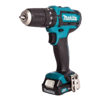
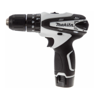
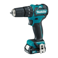
October 2015
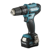
2.2.1.2. ASSEMBLING
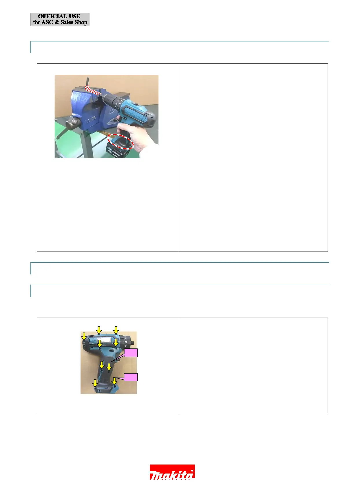
1. Turn Drill chuck clockwise until it seats on the end of the
threaded portion of spindle.
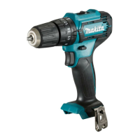
2. Fix Hex wrench 8 as shown.
Note: L-shaped portion of Hex wrench 8 must be fixed
securely.
3. Housing R must be touched on the side surface of
workbench.
Note: Battery portion must not be touched.
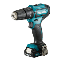
4.
P
ull Switch trigger slowly with Drill mode/Speed change1/
Forward (clockwise) rotation until spindle is locked.
Note: Release the trigger of Switch just after Spindle is
locked. Do not keep on pulling the trigger for longer
than one second.
5. If you reuse the Screw removed from Drill chuck, appl
y
Th
reeBond 1342 or Loctite 243 to the thread of the
Screws.
Note: M6x22(-) Flat head screw: HP331D
M5x22(-) Pan head screw: DF331D
2.2.2. GEAR ASS’Y AND MOTOR SECTION
2.2.2.1. DISASSEMBLING
It is required to remove Drill chuck when replacing Gear assembly.
1. Re
move Housing R (2) by loosening 3x16 Tapping screw
(4) (x9).
10 / 18
 Loading...