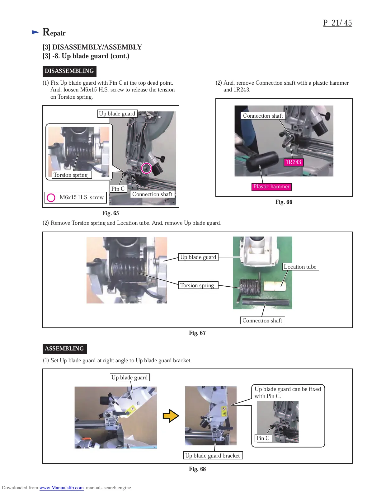
EasyManuals Logo

Makita LS1018L Technical Information

Makita LS1018L
48 pages
To Next Page IconTo Next Page
To Previous Page IconTo Previous Page
Page #24 background imageLoading...
Page #24 background image
P 21/ 45
Repair
[3] DISASSEMBLY/ASSEMBLY
[3] -8. Up blade guard (cont.)
Fig. 68
(1) Set Up blade guard at right angle to Up blade guard bracket.
ASSEMBLING
Fig. 67
(2) Remove Torsion spring and Location tube. And, remove Up blade guard.
DISASSEMBLING
Pin C
Up blade guard
Connection shaft
Plastic hammer
1R243
Up blade guard
Up blade guard
Torsion spring
Location tube
Connection shaft
Up blade guard can be fixed
with Pin C.
Pin C
Up blade guard bracket
M6x15 H.S. screw
(1) Fix Up blade guard with Pin C at the top dead point.
And, loosen M6x15 H.S. screw to release the tension
on Torsion spring.
(2) And, remove Connection shaft with a plastic hammer
and 1R243.
Fig. 66
Fig. 65
Torsion spring
Connection shaft

Other manuals for Makita LS1018L

Questions and Answers:

Question and Answer IconNeed help?

Do you have a question about the Makita LS1018L and is the answer not in the manual?

Makita LS1018L Specifications

General IconGeneral
Input power1430 W
Power sourceAC
Blade bore30 mm
Blade diameter260 mm
Dust bag includedJM23100501
Saw blade includedYes
Idle speed (max)4300 RPM
Weight and Dimensions IconWeight and Dimensions
Depth536 mm
Width825 mm
Height633 mm
Weight19800 g

Related product manuals