16
7.4 Monitored External Entrapment Protection Device Connection
NOTICE
• Do NOT connect more than one (1) monitored entrapment protection device simultaneously on the
MONIT terminals without the use of an interface module.
• Photoelectric cells must be installed facing each other across the door's path within 6” (15 cm) of the
plane of the door and the beam no more than 5-3/4” (14,6 cm) above the floor.
• If a non-monitored photoelectric cell, pneumatic sensing edge or electric sensing edge is used instead of
a monitored entrapment protection device, the operator will ONLY function in C2 (constant-pressure-to-
close) mode. Radio or open/close controls will only open the door.
7.4.1 Monitored Photo Cells
• PHOTO 070: Nema 1 photo cells, through beam type.
(Manufactured by Fraba / UL File # E323938 / p/n: RAY-NS 1001)
• PHOTO 061: Nema 4X photo cells, use in industrial environments, submersible and impact resistant, through
beam type. (Manufactured by Fraba / UL File # E323938 / p/n: OSE-T or OSE-R or OPE)
• PHOTO 065: Nema 4X photo cells, use in industrial environments, heavy-duty housing, retro-reflective type.
(Manufactured by Fraba / UL File # E323938 / p/n: Ray/RT-2004)
• PHOTO 062: Nema 1 photo cells, through beam type (Discontinued).
(Manufactured by Martec / UL File # E325114 / p/n:1266-224)
• PHOTO 064: Nema 4 photo cells, through beam type (Discontinued).
(Manufactured by Martec / UL File # E325114 / p/n: 1266-225)
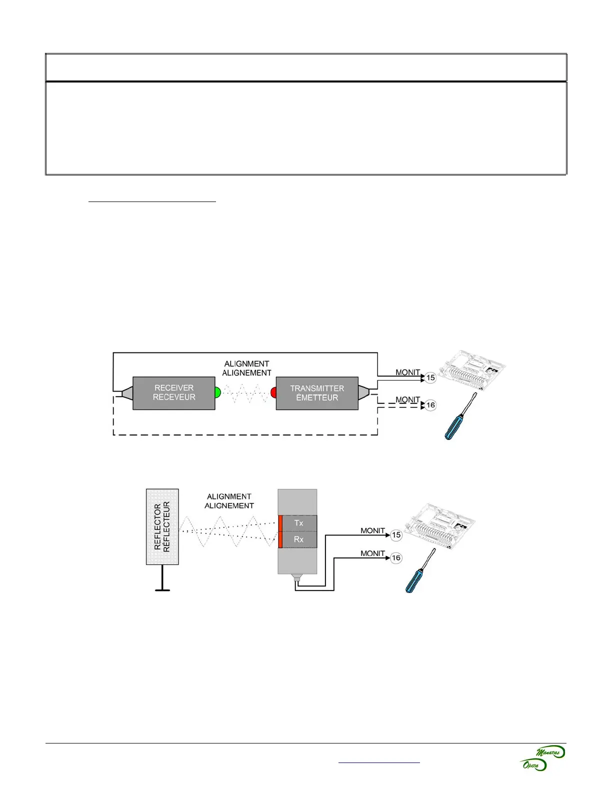
Figure 21 - PHOTO 061 / 062 / 064 / 070 Connection
For further information, please consult the entrapment protection device installation manual for placement of the
sensors.
For technical support, please call 1-800-361-2260 or visit www.manaras.com for more information
Figure 22 - PHOTO 065 Connection