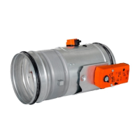
FDMR - Fire damperPage 20 Version 2022-12-20
TPM 165/22
Statement of installations
Placement
wall/ceiling
min. thickness
[mm]
Filling of space
between damper
and wall
Fire resistance Page
In solid wall
construction
100
Mortar or gypsum
EI 120 (v
e
i↔o) S
21
Ablative Coated Batt
EI 90 (v
e
i↔o) S
22
In gypsum wall construction
Mortar or gypsum
EI 120 (v
e
i↔o) S
23
Ablative Coated Batt
EI 90 (v
e
i↔o) S
24
In solid ceiling construction 150 Mortar or gypsum
EI 120 (h
o
i↔o) S
25
■ The fire damper can be integrated into a solid wall
construction made e.g. of normal concrete/masonry,
porous concrete with minimum thickness 100 mm or into
solid ceiling construction made e.g. of normal concrete
with minimum thickness 150 mm.
■ The fire damper can be integrated into a gypsum wall
construction with fire classification EI120 or EI 90.
■ The fire damper can also be integrated outside the wall
construction. Duct and the damper part between the wall
construction and the damper blade (labelled with BUILT
IN EDGE on the protective covering) must be protected
with fire-fighting insulation.
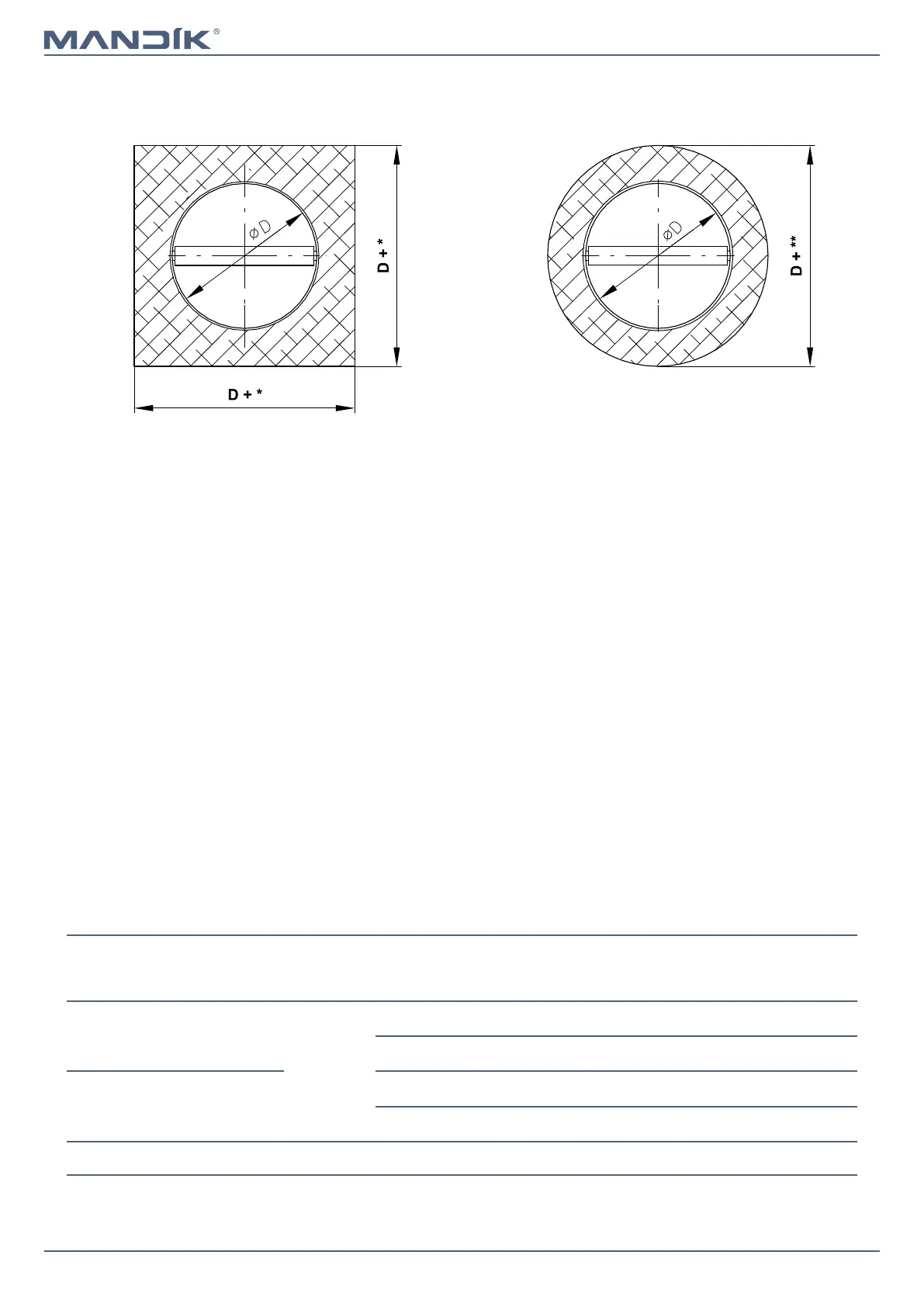
Examples of fire damper installing
Dimensions of installation opening
Mortar or gypsum / Ablative Coated Batt
Dimensions of installation opening
Mortar or gypsum
* Mortar or gypsum
■ min. A(B)+80
■ max. A(B)+300
Ablative Coated Batt
■ min. A(B)+80
■ max. A(B)+260
** Mortar or gypsum
■ min. A(B)+80
■ max. A(B)+300