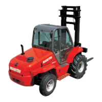
FRONT WHEEL
NOTE : For this operation, we advise you to use the hydraulic jack MANITOU
Reference 505 507 and the safety support MANITOU Reference 554 772.
- Place the jack under the flared axle tube, as near as possible to the wheel and adjust
the jack (Fig. G2/3).
- Lift the wheel until it comes off the ground and put in place the safety support under the
chassis (Fig. G2/4).
- Completely unscrew the wheel nuts and remove them.
- Free the wheel by reciprocating movements and roll it to the side.
- Slip the new wheel on the wheel hub.
- Refit the nuts by hand, if necessary grease them.
- Remove the safety support and lower the lift truck with the jack.
- Tighten the wheel nuts with a torque wrench (See chapter : A - DAILY OR EVERY 10
HOURS SERVICE in paragraph : 3 - MAINTENANCE for tightening torque).
G3 - LIFT TRUCK
TOW
Do not tow the lift truck at more than 25 km/h.
- Put the forward/reverse lever and the gear shift in neutral.
- Release the parking brake.
- Put the warning lights on.
- If the I.C. engine is not running there will be no steering or braking assistance. Operate
the steering and pedal slowly avoiding sudden jerky
movements.
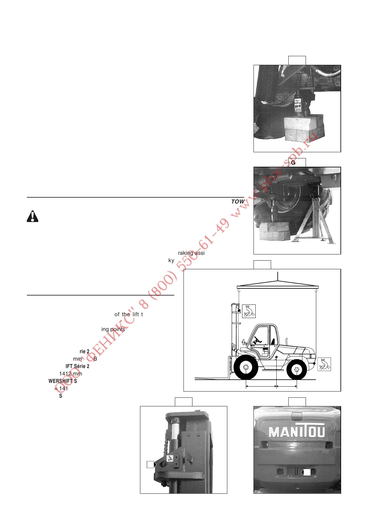
G4 - L
IFT TRUCK
SLING
- Take into account the position of the lift truck gravity
center for lifting (Fig. G4/1).
- Place the hooks in the fastening points provided (Fig. G4/2
and G4/3).
MC 40 POWERSHIFT Série 2
A = 1296 mm B = 767 mm
MC 50 POWERSHIFT Série 2
A = 1412 mm B = 651 mm
MC 60 POWERSHIFT Série 2 + Turbo
A = 1412 mm B = 881 mm
MC 70 POWERSHIFT Série 2 + Turbo
A = 1564 mm B = 929 mm
3 - 32
G4/3G4/2
G2/3
G2/4