648970 IT-EN-NO (18/06/2018)
MRT-X 2150 Privilege Plus ST3A S2 / MRT 2150 Privilege Plus ST4 S2 / MRT-X 2550 Privilege Plus ST3A S2 / MRT 2550 Privilege Plus ST4 S2
3-96
IT
EN
NO
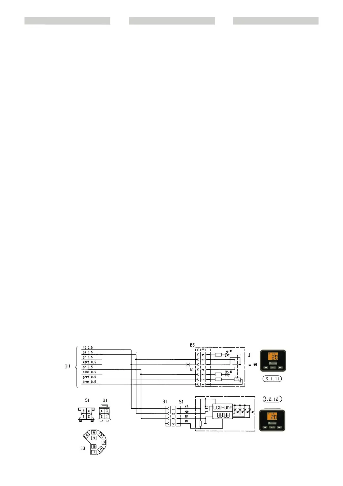
WIRING DIAGRAM KEY
List of components
1.1 Burner engine
1.2 Spark plug
1.5 Heating sensor and
flame sensor
2.1 Control unit
2.2 Fuel dosing pump
2.7 12 Volt: 20A; 24
Volt: 10A Main fuse
2.7.1 5A activation fuse
5.1 Battery
CONTROL ELEMENTS WIRING DIAGRAM
KEY
List of components
3.1.11 Round control device
3.2.12 Mini-timer (optional)
Colour of wires in diagram
sw black
ws white
rt red
ge yellow
gn green
vi violet
br brown
gr grey
bl blue
li lilac
Isolate the wires that are not used.
The various connectors are shown from the
wire input side.
LEGENDA SCHEMA ELETTRICO
Elenco componenti
1.1 Motore bruciatore
1.2 Candela
1.5 Sensore di surriscaldamento e
sensore fiamma
2.1 Centralina di comando
2.2 Pompa dosatrice combustibile
2.7 Fusibile principale12 Volt: 20A; 24
Volt: 10A
2.7.1 Fusibile azionamento 5A
5.1 Batteria
LEGENDA SCHEMA ELETTRICO
ELEMENTI DI COMANDO
Elenco componenti
3.1.11 Dispositivo di comando rotondo
3.2.12 Mini-timer (opzionale)
Colore dei cavi degli schemi
sw nero
ws bianco
rt rosso
ge giallo
gn
verde
vi viola
br marrone
gr grigio
bl azzurro
li lilla
Isolare i cavi non utilizzati.
I vari connettori sono raffigurati dal lato
ingresso cavi.
FORKLARING TIL KOBLINGSSKJEMA
Komponentliste
1.1
Forbrenningsmotor
1.2 Tennplugg
1.5 Overopphetingssensor og
flammesensor
2.1 Kontrollenhet
2.2 Doseringspumpe for drivstoff
2.7 Hovedsikring12 volt: 20A; 24 Volt:
10A
2.7.1 Aktiveringssikring 5A
5.1 Batteri
FORKLARING TIL KOBLINGSSKJEMA
FOR BETJENINGSELEMENTER
Komponentliste
3.1.11 Rund betjeningsenhet
3.2.12 Mini-timer (tilleggsutstyr)
Fargen på ledningene i skjemaene
sw svart
ws hvit
rt rød
ge gul
gn grønn
vi fiolett
br brun
gr grå
bl blå
li lilla
Isoler de ledningene som ikke brukes.
De ulike konnektorene vises fra siden med
ledningsinngangen.
 Loading...