2 - 30
1 - DRIVER'S SEAT
DRIVER’S SEAT (STANDARD)
DESIGNED FOR MAXIMUM COMFORT, THIS SEAT CAN BE ADJUSTED AS FOLLOWS.
LONGITUDINAL ADJUSTMENT
- Unlock the locking lever 1.
- Slide the seat to the desired position.
- Release the lever and be sure it returns to the lock position.
SEAT SUSPENSION ADJUSTMENT
- Refer to the seat's graduation.
- Turn knob 2 according to the driver's weight.
ANGLE ADJUSTMENT OF THE BACK-REST
- Pull the locking lever 3 upwards.
- Tilt the back-rest to the required position.
- Release the lever and be sure it returns to the locking position.
1
2
3
4
5
1
2
3
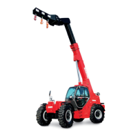
DRIVER'S SEAT (OPTION)
DESIGNED FOR MAXIMUM COMFORT, THIS SEAT CAN BE ADJUSTED AS FOLLOWS.
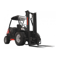
SEAT HEIGHT ADJUSTMENT
- Sit down correctly in the seat.
- Tour the knob 1 according to the desired height, clockwise to rise, anti-clockwise
to lower, ensuring that the green indicator lamp 2 remains visible.
- If indicator lamp 2 is red, re-adjust the height.
NOTE: The seat is designed so as not to require adjustment according to the driver's
weight.
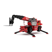
LONGITUDINAL ADJUSTMENT
- Pull lever 3 upwards.
- Slide the seat to the desired position.
- Release the lever and be sure it returns to the lock position.
BACK-REST ANGLE ADJUSTMENT
- Hold the back-rest, push lever 4 backwards and tilt the back-rest to the desired
position.
IMPORTANT
If you do not support the back-rest when making adjustments, it swings completely forwards.
EXTENDING THE HEAD-REST
- The height of the head-rest 5 can be adjusted by pulling it upwards (the notches will click) up to the stop.
- The head-rest can be removed by applying sufficient pressure to pull it off the stop.
647449 (30/11/2015)
MT 732/932 ST3B