National Crane 1-21-2019 Control # 104-07 9-17
1400A SERVICE MANUAL CRANE INSTALLATION
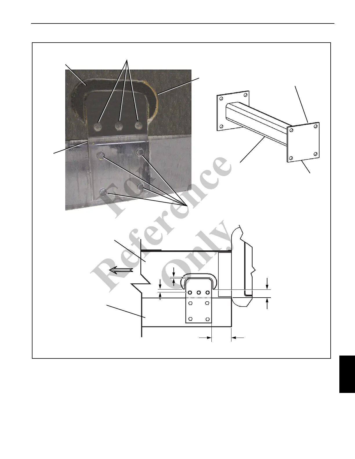
7. Locate and weld the rear strap to the T-box frame
(Figure 9-13).
8. Cut the cross bar to fit (Figure 9-13) inside the truck
frame with the end plate.
9. Weld the end plate to the cross bar.
10. Clamp the cross bar in place and drill four bolt holes
using the Lower Mounting Plate to locate the bolt holes
in the cross bar (Figure 9-13).
11. Tighten all mounting bolts to the proper torque.
Weld
Doubler
Rear Strap
5/8 UNC x 2.25
Grade 8 Bolts
FIGURE 9-13
End Plate
Weld
1 in
(254 mm)
No Weld
0.38 in
(380 mm)
7.5 in (19 cm)
FRONT
Position the Cross Bar
with end plates inside
the truck frame.
Drill end plates after
cross bar is in position.
T-box Frame
Truck Frame
Fo
r
Reference
Only