Section 3 Operation
Part Number 020003315 1/11 3-3
ROCKING CHUTE ICE DISPENSING
On units without the selectable ice option, as the
customer presses the rocking chute, the arm at the top
left rear of the chute pushes upward on the door lock.
The door opens until it contacts the stops in the
mounting brackets. The plastic arm on the ice chute also
activates the lever of the ice dispensing switch. When
activated, the micro switch starts the gear motor. The
gear motor turns the paddle wheel and agitator bar.
SELECTABLE ICE SEQUENCE OF OPERATION
On units equipped with the selectable ice option, as a
customer presses the ice chute or pushes the sanitary lever
towards the unit with their cup, with “Crushed Ice” selected
on the ice selection pad, the rocking chute door lifts and
actuates micro switch which initiates the crushed ice
dispensing process. The micro switch is activated when the
lever is approximately 1/4 inch from reaching the splash
panel of the unit. When activated, the micro switch starts the
gear motor and ice crusher motor. The gear motor turns the
paddle wheel and U-bar agitator. The paddle wheel carries
ice to the crusher assembly. Once the ice reaches the
crusher housing, four stationary blades and three rotating
blades crush the ice and push it through the opening in the
ice crusher housing. The crushed ice then falls through the
opening into the ice chute, and into the customer’s cup. If the
merchandiser is removed no power is available to the
crusher or gear motor and no ice can be crushed and/or
dispensed.
CARBONATION
The purpose of the carbonator is to take regular tap
water at street water pressure (minimum 20 PSI,
maximum 80 PSI, dynamic or flowing pressure) 1/2"
water line and increase the water to beverage system
pressure (usually 100 PSI). This water is then combined
with the CO
2
gas. Because the water and gas are at the
same pressure, the CO
2
will dissolve into the water.
Chilling the mixture before dispensing will assist in
locking the carbon dioxide into the water. After
dispensing, the CO
2
may be unlocked from the liquid.
The CO
2
will gradually leave the liquid due to pressure
and temperature changes.
Components
The components of the carbonator are: water pump, an
electric motor to operate the pump, carbonator tank
where the water and CO
2
mix, and a water level control.
Operation
Carbon Dioxide (CO
2
) leaves the storage tank and
arrives at the carbonator tank through the gas inlet.
Water supply enters the carbonator pump inlet at regular
street water line pressure (minimum 20 PSI, maximum
80 PSI, dynamic or flowing pressure). The water pump
increases the pressure of the water, which allows the
water to flow into the carbonator tank. The CO
2
and the
water mix together in the carbonator to produce the
carbonated water that is then sent to the soda dispenser.
The agitation of the water and CO
2
together in the tank
under high pressure creates the soda water. The quality
of carbonation (percent of CO
2
mixed in the water)
increases as the water temperature decreases and
exposure time increases.
The water level in the carbonator tank is controlled by a
water level control in the tank. This control turns the
pump motor off and on to maintain a preset level of liquid
in the tank. The water level control may be electronic
probes or a mechanical float.
SYRUP DELIVERY SYSTEM
Your syrup location can vary depending on the volume of
beverages served and ease of accessibility. Your beverage
system may set in a back storage room or under the
counter of the dispenser. Configurations are almost
limitless. Check the temperatures expected for the storage
location. Adverse temperatures can affect the storage and
quality of beverage products. It is recommended the
temperature of storage location should not fall below 40°F
(4°C) or rise above 90°F (32°C).
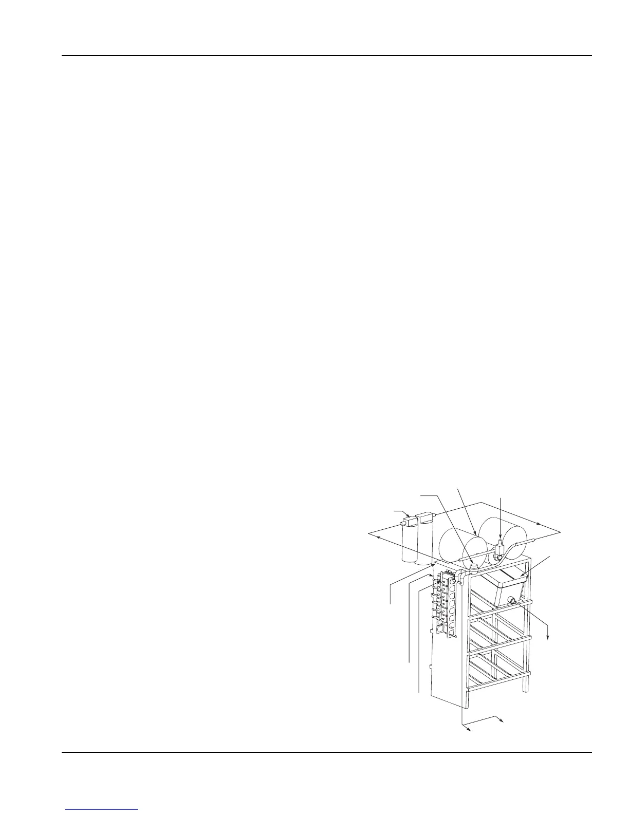
BACK ROOM PACKAGE
From Water Supply
To Noncarbonated Water Inlet Barb
Water to Carbonator Pump
Filter
Water Regulator 40–70 PSI
Booster System (If Required)
To CO
2
Manifold (BIB
Pumps) from
CO
2
Supply
70 PSI
To Syrup Inlet
Barbs on Unit
To BIB Pumps
from BIB
To BIB
Pump
BIB
 Loading...