Grove Published 4-09-2021, Control # 364-11 3-15
RT765E-2 OPERATOR MANUAL OPERATING CONTROLS AND PROCEDURES
Seat Switch (Not Shown)
This switch is located in the seat. An operator must be sitting
in the seat before the crane functions can be activated.
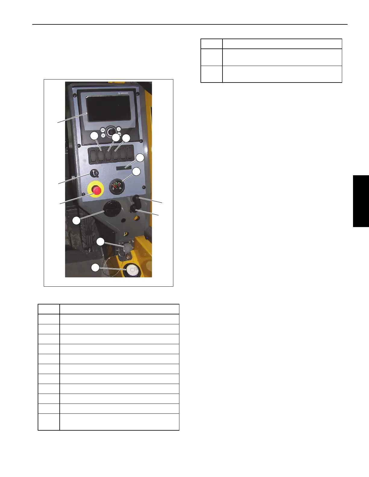
SIDE CONTROL PANEL
Figure 3-10 Item Numbers
Rated Capacity Limiter (RCL) and Work Area
Definition System Control Panel
The RCL and Work Area Definition System Control Panel (1)
(Figure 3-10) is located on the right side of the cab. It
maintains the controls and indicators for the crane’s Rated
Capacity Limiter (RCL) System and Work Area Definition
System. Refer to the RCL Manual for detailed information.
Rated Capacity Limiter (RCL) Bypass Switch
The RCL Bypass (Override) Switch (2) (Figure 3-10) is a
momentary type switch. Turn and hold the key to the ON
position (right) to disengage the RCL controls. Release the
key to allow the RCL controls to re-engage.
The RCL will be bypassed only as long as the switch is in the
ON position.
Turning the key switch to the ON position re-engages the
boom down, telescope out and winch up functions, which are
disabled when an overload condition is sensed by the Rated
Capacity Limiter (RCL). It is important to read and
understand the RCL Override Warning information in the
RCL Operator Manual before using the RCL Bypass switch
(2) or the RCL on/off switch.
Emergency Stop Switch
The crane Emergency Stop Switch (3) (Figure 3-10) is
located on the cab console and is used to shut down the
crane’s engine. Push the red button in to shut down the
engine, which illuminates the Emergency Stop indicator on
the steering column. Rotate the knob and pull out to resume
normal operation.
Transmission Oil Temperature Gauge
The Transmission Oil Temperature (TRANS TEMP) Gauge
(4) (Figure 3-10) is located in the center of the front console
to the left of the steering column. The gauge indicates the
transmission oil temperature on a dual scale calibrated from
60 to 160°C and 140 to 320°F. The gauge receives a signal
from a temperature sending unit in the oil line at the torque
converter.
Turntable Pin Swing Lock Control
The Turntable Pin Swing Lock Control Handle (6)
(Figure 3-10) is located beside on the side control panel. The
purpose of the pin swing lock is to lock the superstructure in
position directly over the front for pick and carry loads.
Item Description
1 Rated Capacity Limiter (RCL) Display
2 Rated Capacity Limiter (RCL) Bypass Switch
3 Emergency Stop Switch
4 Transmission Oil Temp Gauge
5 AC/Heater Vent
6 Turntable Pin Swing Lock Control
7 12 Volt Receptacle
8 Diagnostic Connector
9 Bubble Level Indicator
10 3rd Wrap Indicator (optional)
11
Cold Weather Temperature Indicator
(optional)
7649-7
FIGURE 3-10
1
3
2
5
7
4
8
6
9
10
12
11
13
12
Ambient Temperature LED Indicator
(optional)
13
Telescope Cylinder Charge Indicator (If
Equipped)
Item Description