National Crane Published 12-21-2011 CTRL #050-09 4-1
1300A OPERATOR’S MANUAL SET-UP
SECTION 4
SET-UP
This section contains information on how to perform the
following tasks:
• Set the outriggers.
• Erect the jib.
• Stow the jib
• Remove the jib
• Use multipart reeving.
• Install the hoist cable.
• Install the anti-two-block weight.
• Install a wedge socket.
OUTRIGGER SETUP
Site Selection
The outrigger floats must be on a firm solid surface that is
level. The surface must keep the crane stable and not allow
the stabilizer float to sink or slide. Avoid areas that are:
• uneven
• rocky
• muddy
NOTE: Use the primary level indicator in Section 3,
(Figure 3-1) to verify the accuracy of the secondary
level indicators (Figure 3-1 and Figure 3-2).
To adjust the secondary level indicator:
• Level the crane with the outriggers using the
primary level indicator.
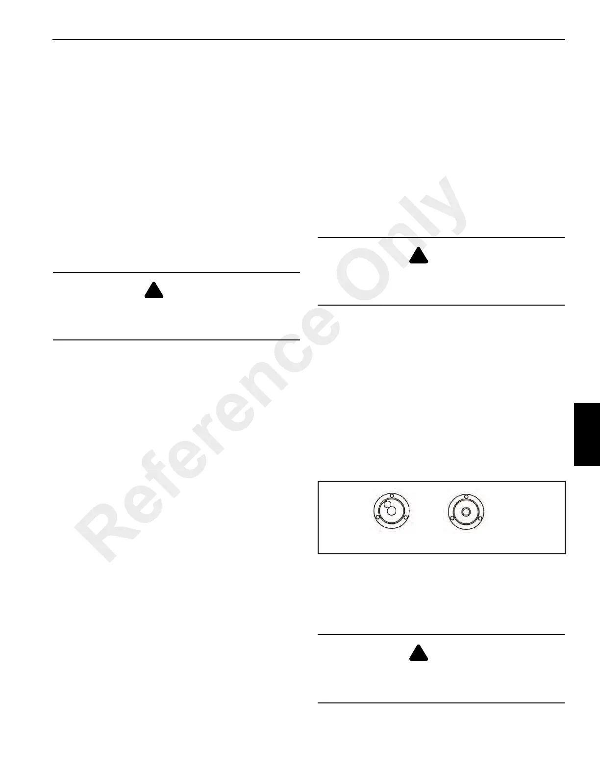
• Adjust the secondary level indicator with the
adjustment screws so that the bubble is in the
center (Figure 4-1).
Setting the Outriggers
The outrigger setup procedure is as follows:
1. Remove the outrigger control box from the stowage
compartment at the rear of the truck Section 3
(Figure 3-1).
2. On the outrigger control box, select the desired outrigger
beam with the extension switch and press the extend/
retract switch to extend the outrigger beam.
3. Set all four outrigger beams to:
a. the fully retracted position. Does not require the
outrigger beams to be extended.
b. the midpoint position. Engage the manual midspan
over-center locks for the midpoint position.
c. the fully extended position.
4. Remove the outrigger floats from the carrying brackets
and place the floats under the stabilizer.
5. Select the desired stabilizer with the stabilizer selector
switch and press the extend/retract switch to extend the
stabilizer.
6. Secure the outrigger floats to the stabilizers with the pins
and clips.
7. Extend all four stabilizers until the truck tires are about
four inches off the ground.
8. Using the level indicator, adjust the stabilizers until the
bubble is in the center of the bulls eye. Do not allow the
tires to touch the ground.
9. Lower the center front stabilizer only after all other
stabilizers are set. Press the front stabilizer switch to
activate and the extend/retract switch to extend. Hold
the extend/retract switch for two seconds after the
stabilizer contacts the ground. The front stabilizer is
automatically set at the correct ground pressure.
DANGER
Do not operate outriggers unless they are visible to either
the operator or a designated signal person to avoid
crushing injury.
DANGER
All four outriggers must either be fully retracted, at the
midpoint, or fully extended, and the LMI set to the correct
position. Failure to do so creates a tipping hazard.
DANGER
After the center front stabilizer is set, it automatically
retracts if any other stabilizer is adjusted. Reset the center
front stabilizer if this occurs.
Not Level Level
FIGURE 4-1
Reference Only

 Loading...


