National Crane Published 12-21-2011 CTRL #050-09 3-5
1300A OPERATORS MANUAL CONTROLS AND OPERATING PROCEDURES
Swing Horn Switch
The swing horn switch (4, Figure 3-3) is located on the crane
cab console. Push the switch to sound the horn button to
warn fellow workers on the job site of pending movement of
crane. An amber LED is illuminated when the switch is on.
Swing Control Lever
The swing control lever (13, Figure 3-3) is located on the left
armrest and controls boom rotation. Push the lever forward
to rotate the boom clockwise and pull back to rotate the
boom counterclockwise.
The swing control lever can be used to slow and stop the
swing by moving the control lever to the opposite direction of
the swing. For example, if the lever is pushed forward for a
clockwise swing, pull the lever back to slow and stop the
swing.
Swing Brake Pedal
The swing brake pedal (10, Figure 3-3) is located on the left
side of the crane cab floor. The brake pedal is used to
activate the swing brake and momentarily hold the turret in
position.
Swing Brake Switch
The swing brake switch is located on the crane cab console
and is used to activate the swing brake and park the turret in
position. Press the switch to activate the swing brake to keep
the turret from rotating. A red LED is illuminated when the
swing brake switch is applied.
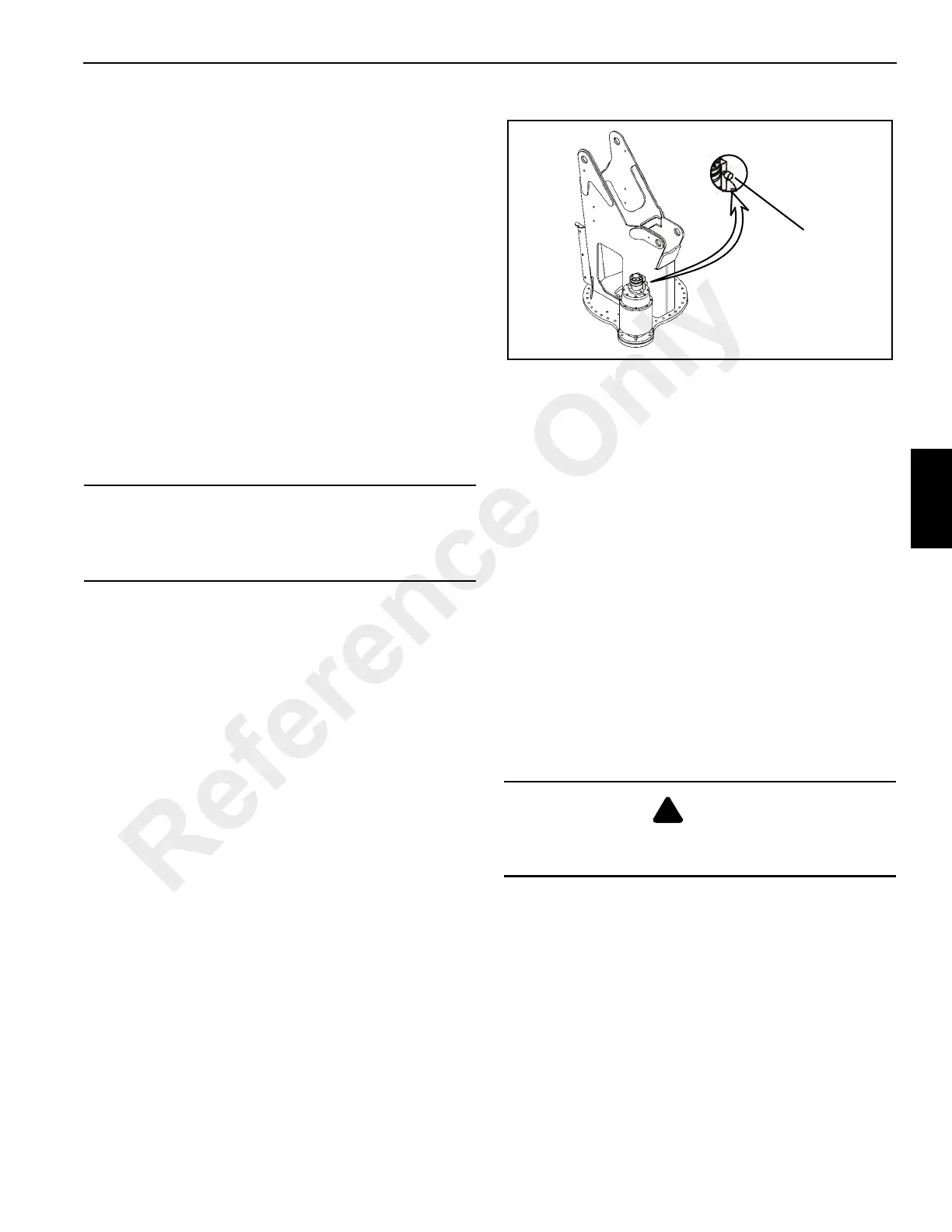
Adjustable Swing Speed Valve
The crane is equipped with an adjustable swing speed valve
(Figure 3-4) that sets the maximum swing speed of the
machine. Loosen the lock collar and turn the dial clockwise
to increase and counterclockwise to decrease speed.
Secure the setting with the lock collar.
Telescope Control Lever (Wireline Control)
The telescope control lever (14, Figure 3-3) is on the left
armrest. Push the lever forward to extend the boom and pull
back to retract the boom. If this machine is equipped with the
wireline option this lever is used to feed and retract the
wireline (see the Boom Telescope Pedal).
Boom Telescope Pedal (Optional)
The telescope foot pedal (12, Figure 3-3) is located on the
crane cab floor and is used to extend and retract the boom.
Rock the pedal forward to extend the boom and back to
retract the boom. This pedal is used with wireline machines,
if this machine is not equipped with the wireline option the
Telescope Control Lever (14) is used to extend and retract
the boom.
Hoist Control Lever
The hoist control lever (17, Figure 3-3) is located on the right
armrest. Push forward to lower the load and pull the lever
back to raise the load.
Burst of Speed (BOS) Switch
The BOS switch (6, Figure 3-3) is located on hoist control
lever and is used to increase speed of the hoist. Press the
switch to activate the BOS function.
Hoist Rotation Indicator (Optional)
The hoist rotation indicator is located on top of the hoist
control lever (17B, Figure 3-3). The indicator is electronically
driven by a signal from an electronic transmitter and sensor
attached to the hoist. A pulsating signal is sensed by the
operator’s thumb during hoist operation.
CAUTION
Do not actuate the Swing Control Lever while the Swing
Brake is engaged, as the turret may push through the
brake. Damage to the swing brake can occur.
DANGER
Payout loadline before extending boom. Failure to do so
may cause the loadline to break or damage the crane.
FIGURE 3-4
Adjustable Swing
Speed Dial
Reference Only

 Loading...


