5-12 3-29-2018 Control # 610-00
OPERATING CONTROLS - AERIAL LIFT NBT40-1 SERIES OPERATOR MANUAL
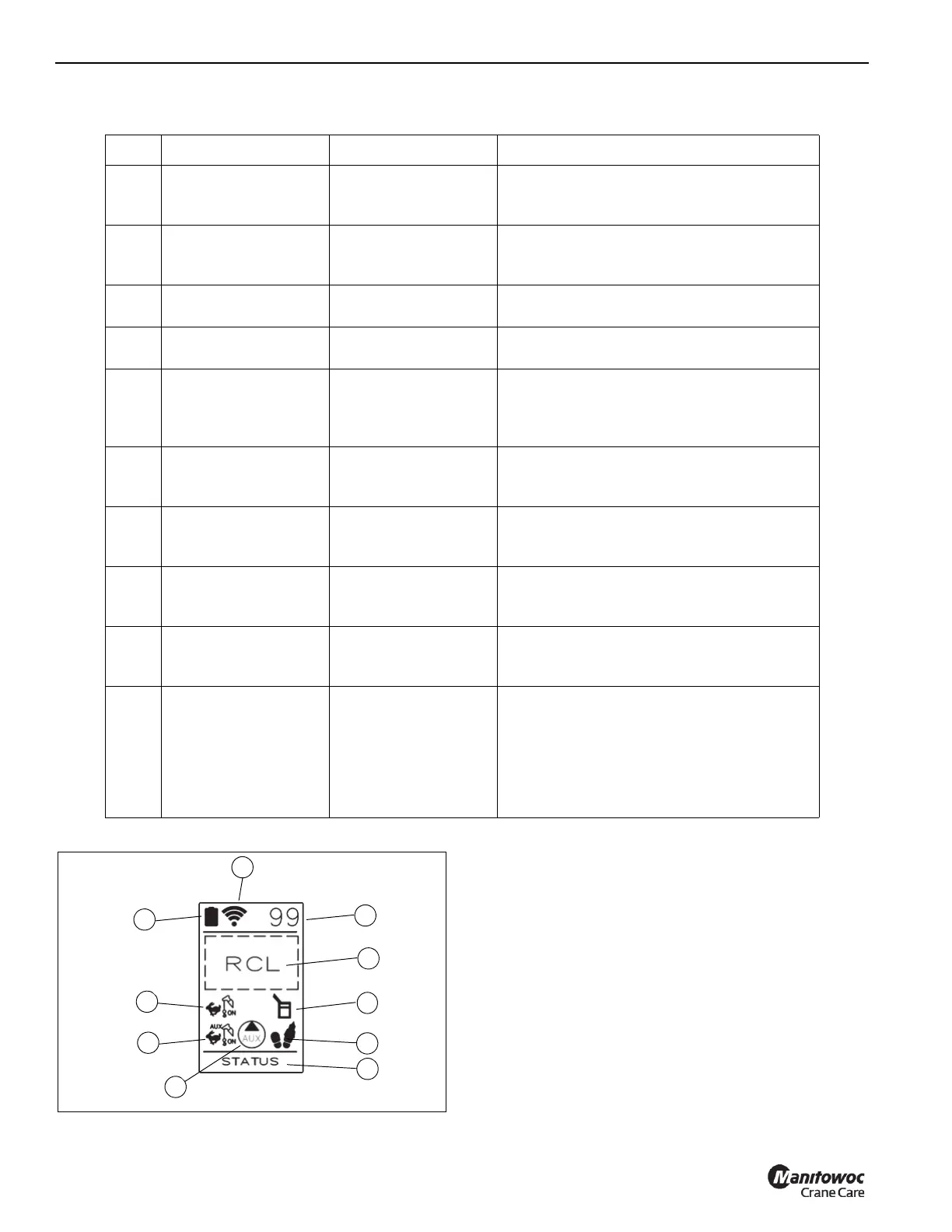
Operator Feedback Screen
Item Symbol/Icon Function Description
1 Figure 5-9 Battery indicator
Real-time display of the rechargable battery.
Audible alarm on the platform controls will
indicate when critically low battery level.
2 Figure 5-9 Signal strength
Signal strength of the wireless communication
between the wireless receiver and the
transmitter.
3 Figure 5-9 Wireless Channel
Indicates the current channel being used for
the wireless transmission.
4 Figure 5-9 Status
Indicates the operational status of the remote
system, software version, etc.
5 Figure 5-9 RCL info display
This area shows all available RCL info and can
be toggled using the button matching the
symbol shown here (Reference item 24 in
Radio Remote Transmitter).
6 Figure 5-9
Main Hoist Enabled &
speed selection
Shown when the Main Hoist is enabled. If high-
speed mode is selected, a rabbit icon is beside
the hoist icon.
7 Figure 5-9
Aux Hoist Enabled &
speed selection
Shown when the Aux Hoist is enabled. If high-
speed mode is selected, a rabbit icon is beside
the hoist icon.
8 Figure 5-9 Aux pump
Shown when the Aux Pump circuit is turned
ON. Shown FLASHING for 2 minutes after use
to allow the pump to cool.
9 Figure 5-9 Aerial Work Platform
Shown to indicate that the RCL has been setup
in an aerial mode and communicating with the
platform controls.
10 Figure 5-9 Footswitch
Shown as a FLASHING icon when in Aerial
Work Platform mode but the switch is not
depressed. Icon disappears when the
footswitch is depressed. Functions must be
activated within 10 seconds of depressing the
footswitch or this will timeout and the icon will
again FLASH.

 Loading...


