22
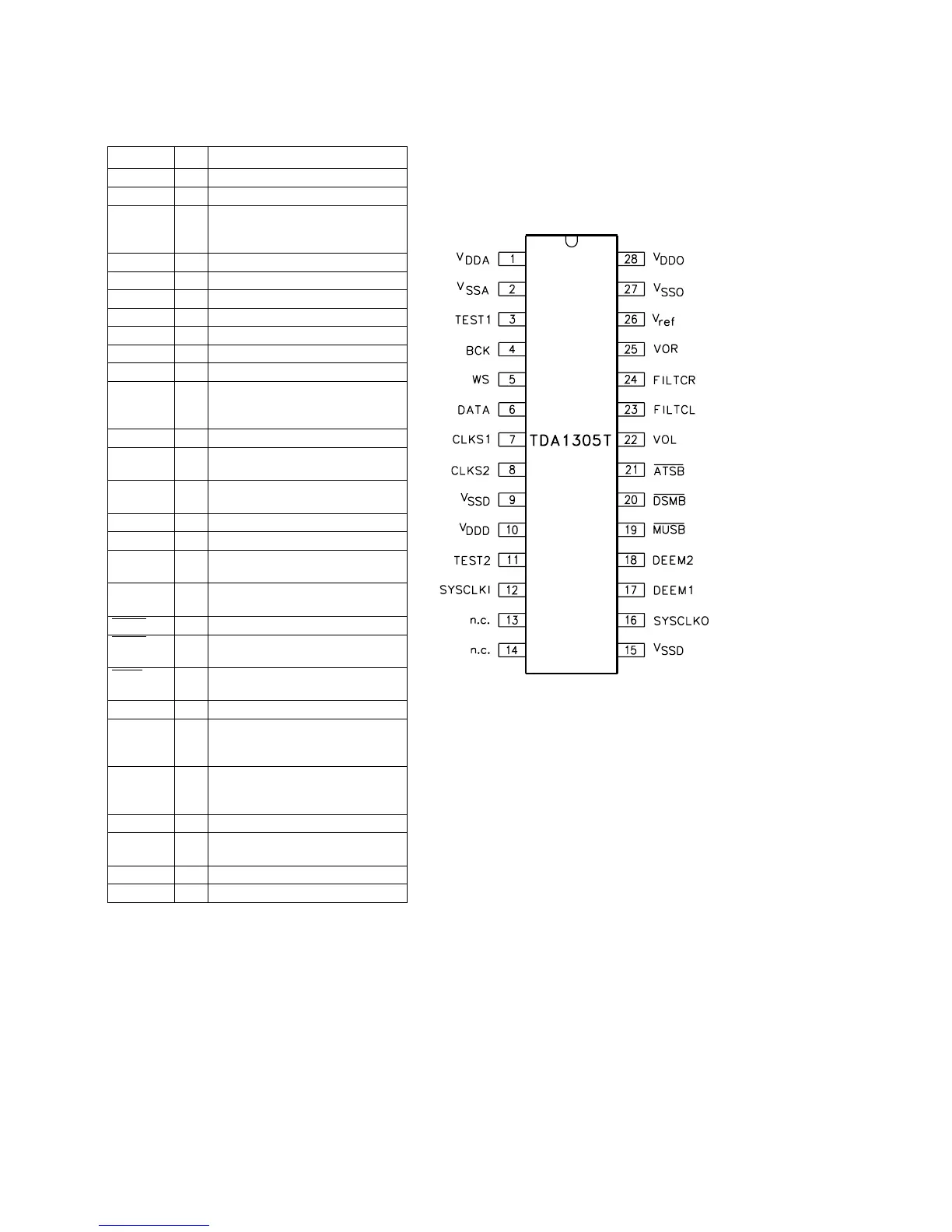
PINNING
SYMBOL PIN DESCRIPTION
V
DDA
1 analog supply voltage
V
SSA
2 analog ground
TEST1 3 test input; pin should be connected
to ground (internal pull-down
resistor)
BCK 4 bit clock input
WS 5 word select input
DATA 6 data input
CLKS1 7 clock selection 1 input
CLKS2 8 clock selection 2 input
V
SSD
9 digital ground
V
DDD
10 digital supply voltage
TEST2 11 test input; pin should be connected
to ground (internal pull-down
resistor)
SYSCLKI 12 system clock input
n.c. 13 not connected (this pin should be left
open-circuit)
n.c. 14 not connected (this pin should be left
open-circuit)
V
SSD
15 digital ground
SYSCLKO 16 system clock output
DEEM1 17 de-emphasis on/off; f
DEEM
32 kHz,
44 kHz and 48 kHz
DEEM2 18 de-emphasis on/off; f
DEEM
32 kHz,
44 kHz and 48 kHz
MUSB 19 mute input (active LOW)
DSMB 20 double-speed mode input
(active LOW)
ATSB 21 12 dB attenuation input
(active LOW)
VOL 22 left channel output
FILTCL 23 capacitor for left channel 1st order
filter function should be connected
between pins 22 and 23
FILTCR 24 capacitor for right channel 1st order
filter function should be connected
between pins 25 and 24
VOR 25 right channel output
V
ref
26 internal reference voltage for output
channels (0.5V
DD
)
V
SSO
27 operational amplifier ground
V
DDO
28 operational amplifier supply voltage
Figure 7-16
Pin configuration and description